Continue to Site

Welcome to EDAboard.com

Welcome to our site! EDAboard.com is an international Electronics Discussion Forum focused on EDA software, circuits, schematics, books, theory, papers, asic, pld, 8051, DSP, Network, RF, Analog Design, PCB, Service Manuals... and a whole lot more! To participate you need to register. Registration is free. Click here to register now.

Oscillator design (Bandgap Current)

analog_design255

Newbie level 4
Newbie level 4
Joined
Dec 13, 2024
Messages
6
Helped
0
Reputation
0
Reaction score
0
Trophy points
1
Visit site
Activity points
48
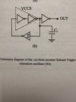
I want to build a relaxation oscillator like the schematic but I should have to use a bandgap reference voltage to create a stable current for the charge and discharge of the capacitor.
I want to use a Schmitt trigger and a feedback path which consists of two inverters. What does it mean with VCCS (Voltage controlled current source?). Are these two inverter the place where I can put the current which was produced by the bandgap voltage reference?
And how can I build a current mirror with the bandgap voltage reference to create the reference constant current? I want to build all in 0.18um CMOS technology.
 

Attachments

  • IMG_76D403FB-1A16-428C-934C-98C784E0440D.jpeg
    IMG_76D403FB-1A16-428C-934C-98C784E0440D.jpeg
    2.1 MB · Views: 16
The bandgap at its heart -is- current mirrors -
jacked in a specific way, for effect.

You may not want an ideal-as-practical bandgap. The rolled-up drifts may want a nonzero TC to
compensate. PTAT, sure, but -what- proportionality?

That says you want to find "what makes it so" for the oscillator care-abouts.

If you have a reference voltage provided then a feedback unity gain buffer can get you "fixed"
currents using a FET follower with source resistance, Isink(t)=VREF(t)/RSET(t). Then mirrors and switches to get you up, down charging current at the timing cap.

Schmitt hysteresis band tends to be real sloppy as it's a 4-transistor tug-of-war with discrepant sizes, sometimes "history effects". A very not-great "reference" to hang the rest of it on. If you're going to the trouble of a true bandgap then you could do better for base reference stability.
The goal is to achieve a frequency of 20MHz with a relative fault of 20%. My Professor means it works with a Schmitt Trigger and an inverter feedback path but I don’t know how many inverters I should use.
The Bandgap reference voltage is already designed but now I have to use this voltage to generate a constant current to charge and discharge the capacitor. I don’t know how to convert this voltage to a reference current and in which place I should include this current.
Are there any papers which discuss this topic?
I have attached the schematic of my designed Schmitt trigger.
Thank you for your help.
 
Last edited:

LaTeX Commands Quick-Menu:

Part and Inventory Search

Welcome to EDABoard.com

Sponsor

Back
Top