Continue to Site

Welcome to EDAboard.com

Welcome to our site! EDAboard.com is an international Electronics Discussion Forum focused on EDA software, circuits, schematics, books, theory, papers, asic, pld, 8051, DSP, Network, RF, Analog Design, PCB, Service Manuals... and a whole lot more! To participate you need to register. Registration is free. Click here to register now.

ORCAD FUNDAMENTAL PROBLEM

Status
Not open for further replies.

ronydc

Full Member level 3
Full Member level 3
Joined
Nov 17, 2005
Messages
166
Helped
4
Reputation
8
Reaction score
3
Trophy points
1,298
Activity points
2,612
jumper orcad

DEAR FRIENDS,
SINCE quite a long.. i m been trying to design a simple single sided pcb in ORCAD.
BUT its not working..!!
I AM quite used to with the software .. but its unable to design a single side pcb ..!!

any how it keeps some 3 nets unrouted..!!and THERE IS NO FACILITY IN THE SOFTWARE ( I FEEL SO) THAT WE CAN MANUALY DRAW A TRACK..!!
EVEN I AM UNABLE TP PUT THE JUMPERS FOR The 3 nets it lefts behind..!!

whts the use of this dull softeware..!!!

I m now fed up with this kinda softwares..!! most of this kind of softwares cant design SINGLE SIDED pcb...!!

and if thay cant make a pcb for single sided by auto routing , thy dont have facility that we can make a track by ourself ..!!!

can some EXPERT show me the guideline .?

--ROny..!

NOTE : PLEASE I aM IN BaDLY NEED TO DESIGN some PCB'S. so help me ..!!
 

howto do manually place with orcad

orcad is not a toy for hobbyists...
professionnals never do single side pcbs I think.
I tried this orcad long time ago but came to the same problem you have with single side pcb: never able to do it...
eagle, proteus, or some other light softwares will do the job.
 

2bet_smt.tch

dear friend.
ofcourse i m not jsut a hobbyist.
i m purely a professional and been in the electronics field since last 16 years.

i dont say in my message that its my workmanship problem but i am infirming to the people at the same level of mine..

that,,
ORCAD HAVE SUCH A PROBLEM. and how professionals like me are making some way out with this situation ----- this is the purpose of my message.

and please if you dont have the way -- keep out of this.
let the EXPERTS SPEAK PLEAST.

-- RONY

NOTE :-- many many many and many professionals design the SINGLE SIDEDED PCBS -- because thts the real CHALLENGE..!!
 

using jumper in orcad layout

Hi!

I'll use my Orcad demo to research this but in the meantime why not give Easy-PC from Number One Systems a go? A (non-savable) free demo is on their website!

Their package is ideally suited to Single-sided PCBs for student/professional use and can insert both Flying Link Wires (e.g., Kynar "mod-wires") and Bare Copper Wire Links and these will be correctly referenced in the Design Rules Check!

A full licence costs about £450 at the moment. They have a Corporate Product called Pulsonix by the way that can also do Chip-On-Board and Embedded Components & High Speed Differential Routing.

I think OrCAD has an equivalent to Easy-PCs Technology Files that will set up a basic Single-Sided PCB with Solder Mask & Silk Screen - I'm sure I've seen it!

Chris Williams
 

orcad smd

ronydc said:
THERE IS NO FACILITY IN THE [OrCAD] SOFTWARE ( I FEEL SO) THAT WE CAN MANUALY DRAW A TRACK..!!
There are facilities for manual routing. Click the "trace" button on the toolbar. Are you trying to auto-route a board? Auto-routing almost always produces unacceptable results.
 

shove track mode demo

dear friend.. kender.
AUTOROUTING IS FORCEFULLY MADE BY orcad
because we cant do MANUAL ROUTING AT ALL ...!!

THTS THE PROBLEM WITH ORCAD.

1> We cant do manual routing and 2> orcad forces us to do the AUTOROUTING ONLY.
===============================
WHY WHY EXPERTS IN THIS FLELD ARE silent .?

-- rony
 

orcad placing component on bottom layer

hi everybody,

i also tried but i didn't get.

Sugession only:

and the same time consider it as double side PCB and send gerber with out considering the csart , if your design is only with through hole components. Otherwise you should place the SMD components on bottom side and take 2 Legnds i.e., top and Bottom. at any cost manual rouing is the best way for Single Side Pcb to get good result.
i think it solves your problem.
Single Side PCB routing is more causious than Double side PCB routing to reduce jumpers.

thanks.
 

orcad bottom top

can some experienced one suggest a good way to design single side pcbs with aany software .?

we are fed up with ORCAD.

-- RONY
 

how to set smd in bottom orcad layer

Even though you claim that you are "professional" however is very obvious that you are not a board designer. Granted OrCad layout is not a very powerful tool but I have done many Boards with BGAs on them, using OrCAD Layout.
Depending on your design there are many PCB tools out there that can do the job for you including Orcad Layout.

M
 

problems happens when preparing a pcb in orcad

Hi all :D
ok this is the way i do for single side boards in orcad layout

1.draw what ever circuit in orcad capture and save it (.MNL file) in appropriate place
N.B if u can assign appropriate foot prints to each and every component then making thing will be bit easy
2.open orcad layout

3. make a new file file-->new

4. then choose appropriate .tech file (in orcad/layout/data)
for through hole components design choose JUMP6035.TCH ,JUMP5535.TCH or JUMP6238.TCH
for smd design 2BET_SMT.TCH (sear for others for more detail)
for thro/smd design 1BET_ANY.TCH ,2BET_THR.TCH or 3BET_ANY.TCH
5. then open your .mnl fie
6. then select top layer
7. using obstacle tool draw a boundary of your pcb as required
8.then drag the component inside to the obstacle u draw (boundary) and place properly
9. goto tool --> layers---->select from spread sheet----->select top layer and set it as jumper layer ( R-click -->properties--> jumper layer radio button)
bottom layer to be routing layer
for all other layers ---> unused routing
10. switch off "online drc"
11. file menu auto-->autoroute--->board ,thous route the board automatically and use jumpers when ever required according to .tech file u choose

12. if u have some unrouted nets then do manual routing by pressing shove track mode, edit segment mode, add/edit route mode buttons (each have specific functions )

13. if u want to use jumper goto tool-->jumper --->new
in there select appropriate foot print ( choose jumper library and there are many jumpers in different widths )
place jumper where u want place and make connection to the jumper with "connection tool " and delete the unnecessary nets (select "connection tool" and L.click on the net where u want to delete and it will ask for confirmation to delete)
and proceed with your manual routing

i usually autorout the board and re adjust the routings and width of traces by manually:D:D
 
orcad remove solder mask track

This tutorial is for you. Tell us, if still you have difficulty.
 

orcad capture 16 auto route wire

dear friend.. kender.
AUTOROUTING IS FORCEFULLY MADE BY orcad
because we cant do MANUAL ROUTING AT ALL ...!!

THTS THE PROBLEM WITH ORCAD.

1> We cant do manual routing and 2> orcad forces us to do the AUTOROUTING ONLY.

You can do manual routing and autorouting both. Orcad is flexible.

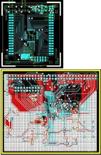
See these boards as an example, 85% was manual route and 15% autoroute.


extremely useful suggestions, especially many thanks to parinda and umery2k75! I have successfully routed a single sided board with jumpers in Orcad!!! awesome!!! :D
 

Hello all,

Can someone kindly post the orcad schematic and footprint of PIC16F877 at your eariest possible.

I need it immediately and fed up of doing google.[/b]
 

It hardly takes 15 minutes to make one yourself. If you don't know how, you can find yourself some tutorial on the internet. I'm out of touch with this software for a long time. I don't remember.
 

Re: problems happens when preparing a pcb in orcad

parinda said:
Hi all :D
ok this is the way i do for single side boards in orcad layout

1.draw what ever circuit in orcad capture and save it (.MNL file) in appropriate place
N.B if u can assign appropriate foot prints to each and every component then making thing will be bit easy
2.open orcad layout

3. make a new file file-->new

4. then choose appropriate .tech file (in orcad/layout/data)
for through hole components design choose JUMP6035.TCH ,JUMP5535.TCH or JUMP6238.TCH
for smd design 2BET_SMT.TCH (sear for others for more detail)
for thro/smd design 1BET_ANY.TCH ,2BET_THR.TCH or 3BET_ANY.TCH
5. then open your .mnl fie
6. then select top layer
7. using obstacle tool draw a boundary of your pcb as required
8.then drag the component inside to the obstacle u draw (boundary) and place properly
9. goto tool --> layers---->select from spread sheet----->select top layer and set it as jumper layer ( R-click -->properties--> jumper layer radio button)
bottom layer to be routing layer
for all other layers ---> unused routing
10. switch off "online drc"
11. file menu auto-->autoroute--->board ,thous route the board automatically and use jumpers when ever required according to .tech file u choose

12. if u have some unrouted nets then do manual routing by pressing shove track mode, edit segment mode, add/edit route mode buttons (each have specific functions )

13. if u want to use jumper goto tool-->jumper --->new
in there select appropriate foot print ( choose jumper library and there are many jumpers in different widths )
place jumper where u want place and make connection to the jumper with "connection tool " and delete the unnecessary nets (select "connection tool" and L.click on the net where u want to delete and it will ask for confirmation to delete)
and proceed with your manual routing

i usually autorout the board and re adjust the routings and width of traces by manually:D:D

Dear Friend,
First of all, thanks a lot for the steps given for single layer board design in orcad. If i follow the steps i can make the board without any problem. But , if i change the footprints of the jumper (e.g. JUMPER300 etc.) - orcad is trying to do the layout without using any jumper (and ultimately failed to acheive 100% routing). Is it possible to make my own jumper library and orcad will use only these jupmers during auto routing (i have tried and failed in Orcad 9)? I can't understand the mistakes i am doing. Pls guide me.

Regards,
Kaushik.
 

Status
Not open for further replies.

Part and Inventory Search

Welcome to EDABoard.com

Sponsor

Back
Top