Vermes
Advanced Member level 4


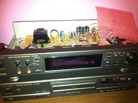
It is a useful device for owners of a digital equalizer (e.g. SH-GE90 from Technics), which despite the digital signal processing does not have digital audio inputs and outputs. It means that using CD player with TOS-LINK output, you have to use analogue stereo output. Thus digital audio sound from CD is converter in the D/A converter to analogue, then again sampled in EQ and after the signal processing, re-changed. Due to the improvement of the quality of the audio track, you can get rid of so frequent digital-analogue and analogue-digital conversion.
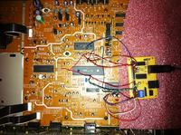
You should use service instruction for SH-GE90 (scheme) and specification of the A/D and D/A converters that are located in the corrector. CS8420 system from Crystal was applied. It has a receiver and transmitter SPDI/F, two audio ports and a sample frequencies converter, all configurable in different ways. In this case, digital signal from the IR receiver goes to the sample frequencies converter (just in case Fs was different from 44,1kHz used in DSP). Then the signal goes through the I2S bus to DSP. From DSP the signal goes to CS8420 via I2S to the optic transmitter. CODEC is clocked by a DSP clock with a frequency of 384*Fs. CS8420 needs to be configured properly and its work should be supervised. A program for PIC12F509 microcontroller was written in Assembler. That program controls the Crystal system through emulated I2C bus. In the corrector's back there is a switch, through which you can select the source of the signal (analogue or digital) – it switches DATA line between CS8420 and the A/D converter in the corrector. Digital signal is simultaneously derived with analogue signal.


Link to original thread (useful attachment) – Wejście i Wyjście optyczne SPDI/F w DSP Technics'a SH-GE90