Continue to Site

Welcome to EDAboard.com

Welcome to our site! EDAboard.com is an international Electronics Discussion Forum focused on EDA software, circuits, schematics, books, theory, papers, asic, pld, 8051, DSP, Network, RF, Analog Design, PCB, Service Manuals... and a whole lot more! To participate you need to register. Registration is free. Click here to register now.

Opinion on this h bridge re-design for 20V please.

Status
Not open for further replies.

boylesg

Advanced Member level 4
Joined
Jul 15, 2012
Messages
1,023
Helped
5
Reputation
10
Reaction score
6
Trophy points
1,318
Location
Epping, Victoria, Australia
Activity points
11,697
I am actually going to have to use this h bridge design because the inputs to my h bridge are coming from a 5V AND gate.
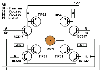
Design20Bridge.gif


My current design will not put the full rail voltage of 12V on to my load.

But if I was to make my rail voltage 20V could you please explain how to recalculate the resistor values.

Also when A is turned on, what voltage and current is the base of the right bottom TIP31 going to see?

'A' is not an emitter follower so I calculate at between 5V and 12V and about 275mA which would be close to saturating that TIP31?
 

Re: Short circuit on this board somewhere- I am at a complete loss!

Hi,

That schematic looks familiar... I recommend you simulate it first. Which website is it from? Can't find it now, there's a good page on a website that explains a lot of h-bridge schematics to be found on the Internet - that don't work, and why they don't work, I haven't been able to track it down now for you, it's a fun read.

The BC547 is 100mA or 200mA for 1mS collector current. You might be able to accomplish the same with two, not four drive transistors - one to top-left PNP and bottom-right NPN, and another for vice-versa.

A way to find solder bridges you can't see with a magnifying glass is to take a reasonable quality photo, like yours in this thread, upload to a PC, zoom in and scan for "invisible" bridges.

Unlikely on your board, once by mistake I discovered that TIP125/TIP120 are easy to send into short-circuit mode with little effort, and very little base current, if the load is insufficient for their power capability.

- - - Updated - - -

Hi,

I just simulated that circuit with an inductor of 1.5mH and 0.5\[\Omega\] resistor (no idea about your motor, but still, one of the below pages used those values for one in the example), and it seems to work okay, with the schematic values the motor current was 1.9A, the TIP31 was 88mA. ...I used no base resistor for the A and B drive BC547s, 'though...

These pages look interesting (maybe?) to simulate a motor realistically/"realistically":

**broken link removed**

DC Motor Model
 

Re: Short circuit on this board somewhere- I am at a complete loss!

Hi,

Not sure of the veracity of this theory, but I'd understood it's bad practice to leave totem-poles floating: if you power that board, and so leave the complementary pair inputs floating, it's possible that both pairs of BJTs are undefined, and on enough to create the H-Bridge "forbidden" input, leading to shorts to ground on one or both sides of the bridge, bypassing the motor.
 

Re: Short circuit on this board somewhere- I am at a complete loss!

Hi,

That schematic looks familiar... I recommend you simulate it first. Which website is it from? Can't find it now, there's a good page on a website that explains a lot of h-bridge schematics to be found on the Internet - that don't work, and why they don't work, I haven't been able to track it down now for you, it's a fun read.

The BC547 is 100mA or 200mA for 1mS collector current. You might be able to accomplish the same with two, not four drive transistors - one to top-left PNP and bottom-right NPN, and another for vice-versa.

A way to find solder bridges you can't see with a magnifying glass is to take a reasonable quality photo, like yours in this thread, upload to a PC, zoom in and scan for "invisible" bridges.

Unlikely on your board, once by mistake I discovered that TIP125/TIP120 are easy to send into short-circuit mode with little effort, and very little base current, if the load is insufficient for their power capability.

- - - Updated - - -

Hi,

I just simulated that circuit with an inductor of 1.5mH and 0.5**broken link removed** resistor (no idea about your motor, but still, one of the below pages used those values for one in the example), and it seems to work okay, with the schematic values the motor current was 1.9A, the TIP31 was 88mA. ...I used no base resistor for the A and B drive BC547s, 'though...

These pages look interesting (maybe?) to simulate a motor realistically/"realistically":

**broken link removed**

DC Motor Model

I am actually using TIP122/127 but without the drive transistors even the base current required for these is starting to push the limits of the AND gate I am using.

So I have left the drive transistors in - I figure that 2 x 12mA or so is better for the AND gate than 2 x 20mA

I used 2SC1815 - I have a heap of these salvaged from tv circuit boards and their pin out is a little more convenient for my board arrangement.
 

Re: Short circuit on this board somewhere- I am at a complete loss!

Hi,

You say AND gate and it's driving capabilities.

You need to select which logic family to use.
In your case a HC type may be more suitable than a LS type.
But there are some with increased drive strength like AHC..

Klaus
 

Re: Short circuit on this board somewhere- I am at a complete loss!

Hi,

You say AND gate and it's driving capabilities.

You need to select which logic family to use.
In your case a HC type may be more suitable than a LS type.
But there are some with increased drive strength like AHC..

Klaus
Ideally I would have used a 12V CMOS quad AND gate....but I just used what I had which was TC74HC08AP.
 

Re: Short circuit on this board somewhere- I am at a complete loss!

Hi,

How much current does the motor need? Just wondering. Datasheet applies to TIP120 through to 127. The base current graphs in the datasheet show 6A from 3mA base current at VCE 3V, and 20 to 30mA at 1.6V VCE. I've measured 4A on a 5V supply with a 1ohm load and 1mA base current for TIP120 and about the same Iout for TIP125. I'm asking to learn something, by the way.
 

I have taken this circuit:

Design20Bridge.gif


And re-designed it for 20V using Multisim:


attachment.php


I am looking particularly at the currents going through the bases of the various transistors and making sure they are about 20-25mA for the TIPs and about 10-15mA for the 2SC1518s

Does any one see any problems with it?

- - - Updated - - -

Hi,

How much current does the motor need? Just wondering. Datasheet applies to TIP120 through to 127. The base current graphs in the datasheet show 6A from 3mA base current at VCE 3V, and 20 to 30mA at 1.6V VCE. I've measured 4A on a 5V supply with a 1ohm load and 1mA base current for TIP120 and about the same Iout for TIP125. I'm asking to learn something, by the way.

The load will be a gate drive transformer primary through a 100nF cap at about 300kHz.

Trying to find an alternative to TCC4422 so I can easily drive the GDT at 20V without worrying about frying the TC4422s (20V is their max rating)

But it appears to be proving just too hard - I tried the exact circuit on my brad board thing and the right hand TIPs suffer shoot through and fry as soon I I connect the power, regardless of the digital inputs.

I just don't comprehend why the circuit seems to work in simulation but not on my bread board.

Think I might have to just buy some more TCC4422s and use less than 20V input to them.
 

Attachments

  • Capture.PNG
    Capture.PNG
    36.9 KB · Views: 304

Wonder why you changed the circuit to darlington transistors, they are hardly fast enough for 300 kHz operation. Achieving sufficient fast switching with BJT will be challenging anyway.

I suggest to make a correct load model (secondary circuit, gate transformer main and leakage inductance) and watch the current and voltage waveforms.

Using gate driver ICs like TC4422 doesn't sound bad. But you shouldn't exceed the supply voltage limit of 18V. Maximum ratings aren't for regular operation.

The datasheet says 4.5V to 18V and then in the table further down it says +20V!

Rather confusing!

So which is it? 18V or 20V?
 

Absolute maximum ratings is a well defined term in electronic components specification, just read the datasheet thoroughly. It explains the term as follows
These are stress ratings only and functional operation of the device at these or any other conditions above those indicated in the operation sections of the specifications is not implied. Exposure to Absolute Maximum Rating conditions for extended periods may affect device reliability.
 

Hi,

Could you use a DPDT relay and a transistor to make the H-Bridge instead, or is it not possible to drive a GDT that way, or maybe due to rest of circuit?
 

Could you use a DPDT relay and a transistor to make the H-Bridge instead, or is it not possible to drive a GDT that way, or maybe due to rest of circuit?

The H-bridge is effectively a pair of SPDT relays; but do you mean to use "real" mechanical relays driven with coils? Forget that!

You need to use suitable transistors that are driven like relays (switches) so that they do not get too hot.
 

Does any one see any problems with it?
Look at the output waveform as FvM suggests.

A gate driver IC is key here and well selected fast mosfets for the 300 kHz.

Look at a discrete H bridge at 300 kHz and its poor waveform.

Schematic:


Voltage across the 1k Load:


- - - Updated - - -

FDG311N is a logic level N channel MOSFET
 

Thanks for that but the point about BJT being to slow for this has been taken - I have given up my idea for a BJT H bridge in place of TC4422s for this application.
 

Status
Not open for further replies.

Part and Inventory Search

Welcome to EDABoard.com

Sponsor

Back
Top