Continue to Site

Welcome to EDAboard.com

Welcome to our site! EDAboard.com is an international Electronics Discussion Forum focused on EDA software, circuits, schematics, books, theory, papers, asic, pld, 8051, DSP, Network, RF, Analog Design, PCB, Service Manuals... and a whole lot more! To participate you need to register. Registration is free. Click here to register now.

OPAMP Current Transformer logic

Status
Not open for further replies.

umery2k75

Advanced Member level 1
Joined
Apr 19, 2006
Messages
434
Helped
42
Reputation
82
Reaction score
16
Trophy points
1,298
Location
Pakistan
Activity points
5,748
I have traced a schematic of a circuit. It's faulty and it doesn't operate.Now this circuit can't be repaired, but I want to learn how it's designed. It's MCU has gone faulty. Any how. I will post the traced schematic today. I don't understand in one part. There was a CT, reading AC current then from that, it goes to a bridge with 100 Hz SINE frequency, because the line frequency is 50Hz/220VAC then it was filtered out by a capactitor and then it was fed into an integrator. I don't understand why he was integrating the current.The circuit was monitoring the current I think. By varying the current, DC level gets shift of a capacitor, then this DC level was fed into an integrator.
 

Is it a true current transformer or a di/dt pickup(Rogowski) coil?
 

    umery2k75

    Points: 2
    Helpful Answer Positive Rating
It's a true Current Transformer. I don't remember the name, it's written at home. I will write the name of CT,when I come home.

Added after 9 minutes:

I'm confused. I think the RED Current Transformer that it may seem to me on the PCB, might be of Air Core Transformer.I read about Rogowski coil, it says that it can measure AC and DC both current and it has Air core. You have given me a HINT. I am calling my friend to study about Rogowski CT and study more about the actual CT circuit. I will be more prepare in my next post. Thankyou FVM :) You are one of the best man around in here.

Added after 1 minutes:

I'm confused, I'm not sure whether it's TRUE Current Transformer or Rogowski Coil.
 

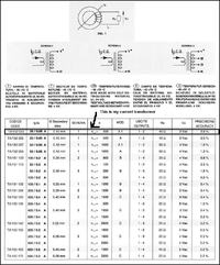
This is the website of the current transformer.

**broken link removed**


When I looked at the datasheet, it appeared as it it's not the Rogowski type current transformer.It's ferrite core. I see the below website, I didn't get differential wave form as shown in the figure, when I put my oscilloscope probe on to it to measure the output of the CT.

**broken link removed**
 

A rogowski coil is always an air coil without a core. It's supported e.g. without an external integrator by the ADI energy measurement chips and
generally a good choice for accurate measurement of high frequency AC currents.

But you have apparently a usual current transformer. So what's special with the circuit?
 

Status
Not open for further replies.

Part and Inventory Search

Welcome to EDABoard.com

Sponsor

Back
Top