Continue to Site

Welcome to EDAboard.com

Welcome to our site! EDAboard.com is an international Electronics Discussion Forum focused on EDA software, circuits, schematics, books, theory, papers, asic, pld, 8051, DSP, Network, RF, Analog Design, PCB, Service Manuals... and a whole lot more! To participate you need to register. Registration is free. Click here to register now.

OP AMP and the amplification

Status
Not open for further replies.

noor84

Member level 5
Member level 5
Joined
Dec 27, 2017
Messages
90
Helped
0
Reputation
0
Reaction score
0
Trophy points
6
Activity points
688
Hi all,

I am confused about the operation of the OP-AMP! please could anyone explain the following?

1- in the Bode plot we measure (DC gain), is the OP AMP used to amplify the DC or AC signal?

2- How would we say the OP AMP always amplify the difference between the two inputs (+ and -), and at the same time, the OP AMP try to make the two inputs equal? so if the two inputs reached to be the same then there is no amplification because the difference is zero?!! so how does the amplification done?

3- How can the OP AMP work when we use the OP AMP as a summing DC signal and apply only DC on the input?

4- Is the OP AMP used to amplify only the AC signals or also DC signals?

I hope I get answers from you.
Thank you in advance.
1) It is the open loop gain of amplifier, we never use the opamp in open loop configuration. There are always negative feedback branch consists of resistor, capacitors etc. The gain is determined by that feedback branch. Do you know the negative feedback?

2) Due to the negative feedback, the difference between inputs becomes zero ideally but there is always an error voltage. In order to obtain zero error voltage, the open loop gain which is the DC gain you mentioned earlier at first question must be high as possible as. If that DC gain in Bode plot (open loop gain) becomes infinite then you get zero voltage between the inputs.

3) Understand the negative feedback

4) I assumed that you asked this question considered we are using opamp in closed loop configuration (in negative feedback). Then, it can amplify both signals with respect to gain of feedback branch if output signal is still in the range of voltage swing.

You should understand the negative feedback thoery very well if you study on opamp. I know that I didnt explain clearly but this is the all I can do it from my phone.
 

1- in the Bode plot we measure (DC gain), is the OP AMP used to amplify the DC or AC signal?

Bode plot is an AC plot

1672162587811.png


x axis is frequenbcy, AC

2- How would we say the OP AMP always amplify the difference between the two inputs (+ and -), and at the same time, the OP AMP try to make the two inputs equal? so if the two inputs reached to be the same then there is no amplification because the difference is zero?!! so how does the amplification done?

The OpAmp does amplify the difference signal, but if feedback is used the OpAmp will drive the
feedback network seeking a stable voltage at the inverting input until it is ~ equal to the non inverting
input. You can solve this analytically or do a sim to show this. Note as the OpAmp G rolls off at higher
frequencies you will see that the input differential V will start rising as the gain loop controlling the
fdbk network runs out of "Gas" so's to speak.

Notice the inv input V starts rising at 10 Hz because the open loop (no fdbk) G of the OpAmp
starts to roll off at 10 Hz. This also shows the concept of virtual ground, the fact that OpAmp
invi input is at virtual ground (~ 0V) when freq is low.

1672163516914.png


1672163699393.png


3- How can the OP AMP work when we use the OP AMP as a summing DC signal and apply only DC on the input?

A summer :

1672163740176.png


Because the inv input is at virtual ground V1, V2, V3 drive currents that flow thur the
feedback R. By superposition then the response is a summed response of each of
these currents x R.


4- Is the OP AMP used to amplify only the AC signals or also DC signals?

Both. Or can be AC coupled such that it only amps the AC.

The beauty of an opamp to reject common mode signals, like sensor in bridges :

1672164143607.jpeg
 
Last edited:

1) It is the open loop gain of amplifier, we never use the opamp in open loop configuration. There are always negative feedback branch consists of resistor, capacitors etc. The gain is determined by that feedback branch. Do you know the negative feedback?

2) Due to the negative feedback, the difference between inputs becomes zero ideally but there is always an error voltage. In order to obtain zero error voltage, the open loop gain which is the DC gain you mentioned earlier at first question must be high as possible as. If that DC gain in Bode plot (open loop gain) becomes infinite then you get zero voltage between the inputs.

3) Understand the negative feedback

4) I assumed that you asked this question considered we are using opamp in closed loop configuration (in negative feedback). Then, it can amplify both signals with respect to gain of feedback branch if output signal is still in the range of voltage swing.

You should understand the negative feedback thoery very well if you study on opamp. I know that I didnt explain clearly but this is the all I can do it from my phone.


Thank you so much [I][B]kirito[/B][/I] for your reply,

1) It is the open loop gain of amplifier, we never use the opamp in open loop configuration. There are always negative feedback branch consists of resistor, capacitors etc. The gain is determined by that feedback branch. Do you know the negative feedback?

In the Bode plot, the x-axis starts from zero hertz (DC)!!!
I have some knowledge about the feedback (not too much), but when we use the bode plot we can see the DC value (zero hertz) even with a close loop.


2) Due to the negative feedback, the difference between inputs becomes zero ideally but there is always an error voltage. In order to obtain zero error voltage, the open loop gain which is the DC gain you mentioned earlier at first question must be high as possible as. If that DC gain in Bode plot (open loop gain) becomes infinite then you get zero voltage between the inputs.

If we suppose we have an infinity open loop gain, then the difference between two inputs is zero then (Vo=Av (V1-V2) ) and (V1-V2)=0!! then there is no amplification!! this is my question, how will work the OP AMP then if the difference is zero?

3- How can the OP AMP work when we use the OP AMP as a summing DC signal and apply only DC on the input?

here I mean, the OP AMP deal with AC to amplify, how does the OP AMP work with DC input voltage if it is designed to amplify?


I hope you answer me and thank you once again.
--- Updated ---

1- in the Bode plot we measure (DC gain), is the OP AMP used to amplify the DC or AC signal?

Bode plot is an AC plot

View attachment 180400

x axis is frequenbcy, AC

2- How would we say the OP AMP always amplify the difference between the two inputs (+ and -), and at the same time, the OP AMP try to make the two inputs equal? so if the two inputs reached to be the same then there is no amplification because the difference is zero?!! so how does the amplification done?

The OpAmp does amplify the difference signal, but if feedback is used the OpAmp will drive the
feedback network seeking a stable voltage at the inverting input until it is ~ equal to the non inverting
input. You can solve this analytically or do a sim to show this. Note as the OpAmp G rolls off at higher
frequencies you will see that the input differential V will start rising as the gain loop controlling the
fdbk network runs out of "Gas" so's to speak.

Notice the inv input V starts rising at 10 Hz because the open loop (no fdbk) G of the OpAmp
starts to roll off at 10 Hz. This also shows the concept of virtual ground, the fact that OpAmp
invi input is at virtual ground (~ 0V) when freq is low.

View attachment 180401


View attachment 180402

3- How can the OP AMP work when we use the OP AMP as a summing DC signal and apply only DC on the input?

A summer :

View attachment 180403

Because the inv input is at virtual ground V1, V2, V3 drive currents that flow thur the
feedback R. By superposition then the response is a summed response of each of
these currents x R.


4- Is the OP AMP used to amplify only the AC signals or also DC signals?

Both. Or can be AC coupled such that it only amps the AC.

The beauty of an opamp to reject common mode signals, like sensor in bridges :

View attachment 180404
Thank you for your reply,

Bode plot is an AC plot,
In the Bode plot, we have zero hertz (DC)?!! can you explain this point, please?


1672162587811.png
 
Last edited:

Thank you so much [I][B]kirito[/B][/I] for your reply,

1) It is the open loop gain of amplifier, we never use the opamp in open loop configuration. There are always negative feedback branch consists of resistor, capacitors etc. The gain is determined by that feedback branch. Do you know the negative feedback?

In the Bode plot, the x-axis starts from zero hertz (DC)!!!
I have some knowledge about the feedback (not too much), but when we use the bode plot we can see the DC value (zero hertz) even with a close loop.


2) Due to the negative feedback, the difference between inputs becomes zero ideally but there is always an error voltage. In order to obtain zero error voltage, the open loop gain which is the DC gain you mentioned earlier at first question must be high as possible as. If that DC gain in Bode plot (open loop gain) becomes infinite then you get zero voltage between the inputs.

If we suppose we have an infinity open loop gain, then the difference between two inputs is zero then (Vo=Av (V1-V2) ) and (V1-V2)=0!! then there is no amplification!! this is my question, how will work the OP AMP then if the difference is zero?

3- How can the OP AMP work when we use the OP AMP as a summing DC signal and apply only DC on the input?

here I mean, the OP AMP deal with AC to amplify, how does the OP AMP work with DC input voltage if it is designed to amplify?


I hope you answer me and thank you once again.
--- Updated ---


Thank you for your reply,

Bode plot is an AC plot,
In the Bode plot, we have zero hertz (DC)?!! can you explain this point, please?


1672162587811.png
1) In log scale bode plot, 0 Hertz doesn't exist. It is called as DC gain because the frequency is too low so that we can act like we have dc signal in this frequency range. If you have a signal with 0 hertz in frequency domain what do you have in time domain? A signal starts from -infinite and keeps to + infinite, can we have that signal?

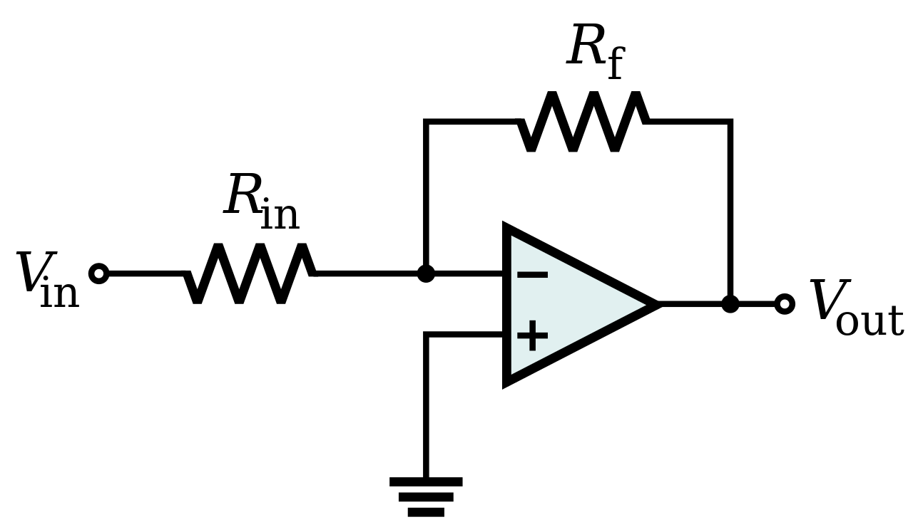
2) Those inputs are not your input pins where you give your signal to be amplifed. Think inverting configuration with Rin and Rf resistances, you give the Vin from left side of Rin and you get the Vout as -(Rf/Rin)*Vin. The opamp is able to give that Vout by forcing the error voltage is zero (Vin+ - Vin- = 0). You can consider the steps one by one. When Vin is increased, Vin- is increased. Then, opamp sensed this increment at the Vin-. Second, (Vin+ - Vin- ) < 0. Third, the opamp gives negative voltage at the output. Here, the amplification you mentioned is realized. Due to the voltage difference between Vin+ and Vin-, the amplification can be realized and Vout is decreased. Fourth, due to decreasing in Vout, it drains current through Rf from Vin- and the Vin- lose voltage until Vin+ is higher than Vin- ( Vin+ > Vin-). Fifth, now it has this situtation (Vin+ - Vin- > 0 ) so opamp gives positive voltage at the output again here that amplification realized. Those steps realize again and again until Vin+ - Vin- = 0 . At this point, opamp has a balance between its input terminals.
File:Op-Amp Inverting Amplifier.svg - Wikipedia


3) OpAmp can amplify both dc singals and ac signals.
 

An OpAmp (virtually all) is DC coupled in signal chain, and has an AC response as well.

So it amps both DC and AC.

Bode plots, since their MAIN focus is on AC performance, typically DO NOT SHOW
0 Hertz, they show sub hertz, but not TYPICALLY 0 Hertz. Dont get hung up on this,
the OpAmp (MOST) amplify DC and AC both. End of story.

If we suppose we have an infinity open loop gain, then the difference between two inputs is zero then (Vo=Av (V1-V2) ) and (V1-V2)=0!! then there is no amplification!! this is my question, how will work the OP AMP then if the difference is zero?

3- How can the OP AMP work when we use the OP AMP as a summing DC signal and apply only DC on the input?

here I mean, the OP AMP deal with AC to amplify, how does the OP AMP work with DC input voltage if it is designed to amplify?

Its only zero if the OpAmp gain is < infinity, which is ALWAYS the case. So there is a small error V
ALWAYS present because the OpAmp open loop G is finite. And as frequency is raised its G drops
so that V starts to rise and causes errors that one accounts/analyzes for.

Here is an analysis that covers the approximation :


Pay attention to Av is the low frequency, DC gain of opamp, known as Aol.

1672176759956.png


Now your question, if opamp G is infinite (THERE ARE NO INFINITE G OPAMPS IN THIS GALAXY)
why would the amplifying circuit not amplify ? The amplifying circuitry does not quit working, it
just has nothing to amplify in that case. But again, there is no infinite G opamps and you have
noise due to basic thermal processes that cause a non zero differential V to occur. Thats
another issue to deal with. And we have not discussed ALL opamps have a non zero offset
V at the differential input to deal with.

1672177579226.png


Regards, Dana.
 
Last edited:
An OpAmp (virtually all) is DC coupled in signal chain, and has an AC response as well.

So it amps both DC and AC.

Bode plots, since their MAIN focus is on AC performance, typically DO NOT SHOW
0 Hertz, they show sub hertz, but not TYPICALLY 0 Hertz. Dont get hung up on this,
the OpAmp (MOST) amplify DC and AC both. End of story.


Its only zero if the OpAmp gain is < infinity, which is ALWAYS the case. So there is a small error V
ALWAYS present because the OpAmp open loop G is finite. And as frequency is raised its G drops
so that V starts to rise and causes errors that one accounts/analyzes for.

Here is an analysis that covers the approximation :


Pay attention to Av is the low frequency, DC gain of opamp, known as Aol.

View attachment 180409


Now your question, if opamp G is infinite (THERE ARE NO INFINITE G OPAMPS IN THIS GALAXY)
why would the amplifying circuit not amplify ? The amplifying circuitry does not quit working, it
just has nothing to amplify in that case. But again, there is no infinite G opamps and you have
noise due to basic thermal processes that cause a non zero differential V to occur. Thats
another issue to deal with. And we have not discussed ALL opamps have a non zero offset
V at the differential input to deal with.

View attachment 180410


Regards, Dana.

Thank you Dana for your reply,
Please, see the attached paper that talks about the design of two-stage OP-AMP and the paper mentioned DC gain many times, especially on page 3, I don't understand what this paper means by DC gain as I am a beginner designer.


Could you please give me the name of the book that contains the final picture that you attached?

Thank you once again for your help.
Regards.
 

Attachments

  • Paper.pdf
    773.4 KB · Views: 187

Final pic was from simple google search.

Foundation books on OpAmps :


More advanced topics :


Regards, Dana.
 

Final pic was from simple google search.

Foundation books on OpAmps :


More advanced topics :


Regards, Dana.

Thank you DANA,

Please, you did not answer my question in the previous email, may I get the answer, please?

my equation was :
"Please, see the attached paper that talks about the design of two-stage OP-AMP and the paper mentioned DC gain many times, especially on page 3, I don't understand what this paper means by DC gain as I am a beginner designer."


Regards
 

Attachments

  • Paper.pdf
    773.4 KB · Views: 200

Hi,

DC gain in the meaning of 0Hz is a theoretical value.
0Hz has an infinite period time, so if you use this signal you need infinite time to measure it. Impossible.

So DC gain represents "very low frequency" gain. On OPAMPs the gain for "very low frequency" is flat. (Look at the bode plot).
So it usually is the same for 1Hz, 0.1Hz, 0.01Hz ... and so on.

*****
Similar with "zero input voltage"
at the same time, the OP AMP try to make the two inputs equal?
You phrase it correctly "the Opamp tries".

Let's see it the other way round: use an Opamp with 100dB open loop gain and +/-5V meaningful output voltage range.
Now calculate back to the differential voltage at the input:
100dB is a factor of 100,000
+/-5V / 100,000 = +/-0.00005V or 0.05mV or 50uV
So the Opamp is able to truely amplify input voltage in the range of +/-50uV.
Every "higher" input voltage results in saturated (=not regulated) outputs.
With Opamps you don't want saturated outputs, (Saturated outputs are for comparators)
...thus the meaningful input voltage is just +/- 50uV ... this is pretty close to zero input voltage.

On real opamps you have input noise and input offset errors, often these errors are bigger than the "ideal" differential input voltage range during normal operation. Basically if the signal is smaller than it's uncertainties(errors), you may call it "zero".

Klaus
 

Your question: "If we suppose we have an infinity open loop gain, then the difference between two inputs is zero then (Vo=Av (V1-V2) ) and (V1-V2)=0!! then there is no amplification!! this is my question, how will work the OP AMP then if the difference is zero?"

In short (again): The difference is NEVER zero.
However, during most of the calculations we assume that the difference is zero because the error by doing this is much much smaller if we compare it with all the other neglections and simplifications and parts tolerances (for example, normally we neglect finite input/output impedances) .
 
Hi,

DC gain in the meaning of 0Hz is a theoretical value.
0Hz has an infinite period time, so if you use this signal you need infinite time to measure it. Impossible.

So DC gain represents "very low frequency" gain. On OPAMPs the gain for "very low frequency" is flat. (Look at the bode plot).
So it usually is the same for 1Hz, 0.1Hz, 0.01Hz ... and so on.

*****
Similar with "zero input voltage"

You phrase it correctly "the Opamp tries".

Let's see it the other way round: use an Opamp with 100dB open loop gain and +/-5V meaningful output voltage range.
Now calculate back to the differential voltage at the input:
100dB is a factor of 100,000
+/-5V / 100,000 = +/-0.00005V or 0.05mV or 50uV
So the Opamp is able to truely amplify input voltage in the range of +/-50uV.
Every "higher" input voltage results in saturated (=not regulated) outputs.
With Opamps you don't want saturated outputs, (Saturated outputs are for comparators)
...thus the meaningful input voltage is just +/- 50uV ... this is pretty close to zero input voltage.

On real opamps you have input noise and input offset errors, often these errors are bigger than the "ideal" differential input voltage range during normal operation. Basically if the signal is smaller than it's uncertainties(errors), you may call it "zero".

Klaus

Hi Klaus,

Thank you so much for your reply, it is very clear now.

Regards.
--- Updated ---

Your question: "If we suppose we have an infinity open loop gain, then the difference between two inputs is zero then (Vo=Av (V1-V2) ) and (V1-V2)=0!! then there is no amplification!! this is my question, how will work the OP AMP then if the difference is zero?"

In short (again): The difference is NEVER zero.
However, during most of the calculations we assume that the difference is zero because the error by doing this is much much smaller if we compare it with all the other neglections and simplifications and parts tolerances (for example, normally we neglect finite input/output impedances) .

Hi LvW,

Thank you for your reply.
--- Updated ---

1) In log scale bode plot, 0 Hertz doesn't exist. It is called as DC gain because the frequency is too low so that we can act like we have dc signal in this frequency range. If you have a signal with 0 hertz in frequency domain what do you have in time domain? A signal starts from -infinite and keeps to + infinite, can we have that signal?

2) Those inputs are not your input pins where you give your signal to be amplifed. Think inverting configuration with Rin and Rf resistances, you give the Vin from left side of Rin and you get the Vout as -(Rf/Rin)*Vin. The opamp is able to give that Vout by forcing the error voltage is zero (Vin+ - Vin- = 0). You can consider the steps one by one. When Vin is increased, Vin- is increased. Then, opamp sensed this increment at the Vin-. Second, (Vin+ - Vin- ) < 0. Third, the opamp gives negative voltage at the output. Here, the amplification you mentioned is realized. Due to the voltage difference between Vin+ and Vin-, the amplification can be realized and Vout is decreased. Fourth, due to decreasing in Vout, it drains current through Rf from Vin- and the Vin- lose voltage until Vin+ is higher than Vin- ( Vin+ > Vin-). Fifth, now it has this situtation (Vin+ - Vin- > 0 ) so opamp gives positive voltage at the output again here that amplification realized. Those steps realize again and again until Vin+ - Vin- = 0 . At this point, opamp has a balance between its input terminals.
File:Op-Amp Inverting Amplifier.svg - Wikipedia


3) OpAmp can amplify both dc singals and ac signals.

Hi Kirito,

Thank you for the explanation.


Regards.
 
Last edited:

Status
Not open for further replies.

Similar threads

Part and Inventory Search

Welcome to EDABoard.com

Sponsor

Back
Top