Continue to Site

Welcome to EDAboard.com

Welcome to our site! EDAboard.com is an international Electronics Discussion Forum focused on EDA software, circuits, schematics, books, theory, papers, asic, pld, 8051, DSP, Network, RF, Analog Design, PCB, Service Manuals... and a whole lot more! To participate you need to register. Registration is free. Click here to register now.

Offline Voltage Mode Half Bridge for battery charging?

cupoftea

Advanced Member level 6
Joined
Jun 13, 2021
Messages
3,122
Helped
62
Reputation
124
Reaction score
139
Trophy points
63
Visit site
Activity points
16,256
Hi,
Have just finished schem for Offline (400Vin) two transistor forward (in current mode) for
charging battery at 48V and 5A.

However, our contractor says it should be changed for a voltage mode Half Bridge.
Stating how the Half Bridge can have a smaller transformer. Also that Half Bridge
lends itself better to bootstrap hi side drive chips. Also that there are cheap
Half Bridge driver chips available which also do the synchronous rectification signals
aswell. (There are no chips for Two Transistor forward which also give the synchronous rectifier signals).

Anyway, this isn't the point, would you agree?, "voltage mode" is poor for a battery charger, since the
battery is an enormous capacitance of unknown capacitance value (from charge to charge).
As such, the normal , and essential voltage mode frequency compensation method of putting two zeros at the output double pole
frequency is impossible, because one simply cannot know where the output double pole will be.

Would you agree, voltage mode half bridge is not the way to go for battery charging?
 
For charging a battery, you certainly need control of output current (even if that just means having a well defined current limit). However, peak current mode control by itself is not suitable for controlling charger current, you really want to control average output current.

You can certainly use either a voltage mode or peak current mode control pwm controller as a starting point, but you will need some other control loop wrapped around it in order to properly control output current.
 
You can certainly use either a voltage mode or peak current mode control pwm controller as a starting point, but you will need some other control loop wrapped around it in order to properly control output current.
Thanks, our take is that if one is using a current sensor downstream of the main output capacitor bank of the Voltage Mode Half Bridge, then in effect that is akin to regulating the output voltage on the capacitor bank anyway.
Ie, if one is regulating the output current from the voltage mode full bridge, to the battery, then that is effectively the same as regulating the output voltage of the voltage mode full bridge. Because the current sensor is downstream of the output capacitor bank and so regulating the current there does not cancel out the voltage mode output double pole. Whereas current mode control does cancel out one of the output poles.

So...that dreaded output stage double pole will still be there. And so must be cancelled by two zeros in the feedback compensator. But where do you put the two zero's?...because the power stage will still comprise the battery...and thats an enormous capacitance......and an unknown capacitance....so, supposing you are using a voltage mode half bridge...AND...you are regulating the output current into a battery.....THEN.....you still have the voltage mode output double pole issue to solve.....(otherwise you will get instability)........so the question is......with "voltage mode output current regulated battery charger", where do you put the compensator zeros?....at what frequencys do you put them?
If they dont get put at the right frequency than you will get instability.....even if you are ultimately regulating the eventual output current of the converter.

So do you agree? Voltage Mode Half Bridge Battery Charger is not a good way to go.?
 
our take is that if one is using a current sensor
nothing about a current sensor in post#1

It seems like you have two control loops now. One voltage mode and one with current sensing.

--> To clarify your situation a sketch would be helpful.

Klaus
 
It seems like you have two control loops now. One voltage mode and one with current sensing.

--> To clarify your situation a sketch would be helpful.
Thanks, ill bring the sketch soonest.
Yes so if you think of a "Normal" output divider being used to regulate a "normal" voltage mode half bridge thats regulating its output voltage....well now, get rid of the output divider, and instead regulate the voltage across the sense resistor that feeds into the battery. (ie regulate the current from the "voltage mode half bridge" to the battery.)

So there's no more feedback loops been added...i have just subbed the output divider for the current sense resistor.
It is still voltage mode because ultimately the error voltage (from the error amplifier) gets fed to the PWM comparator along with the synthesized ramp.

(Though of course, there will be an overvoltage clamp, as is the case for any output current regulated SMPS, but thats not relevant in this bit of discussion.)
 
Hi,
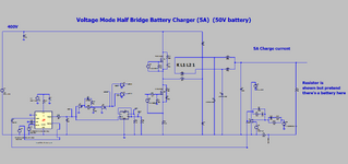
To clarify your situation a sketch would be helpful.
Thanks, please find as attached..

The Voltage Mode Half Bridge Battery charger is as attached
LTspice and Schem attached.
(An actual battery load is not shown as its an enormous capacitance of unknown capacitance)
 

Attachments

  • Half Bridge _CCM Voltage Mode_Batt Charger.zip
    3.1 KB · Views: 20
  • Half Bridge Voltage mode battery charger.png
    Half Bridge Voltage mode battery charger.png
    77.7 KB · Views: 22
First of all, the simulation doesn't work for me. U2 oscillates wildly. Replacing it with a simple universal opamp model seems to fix it.
Second, I wouldn't call this a battery charger. It's just a current source, with no voltage control. I'm not sure what battery chemistry this is meant for, but I'm sure no battery would survive long with it.
 
First of all, the simulation doesn't work for me. U2 oscillates wildly. Replacing it with a simple universal opamp model seems to fix it.
Thanks, thats interesting, it works on my computer, and in LTspice i am using "modified trap, Alternate, 4".

Second, I wouldn't call this a battery charger.
Thanks, certainly you are right about that...its just to give the general jist of a voltage mode converter being used to control a current into something.
As you suspected, there is some extra "reader adaptation" needed here for the situation to be investigated.
Klaus asked for a schem, and so i showed enough to get the idea across. Klaus wanted to see the feedback loop. In truth i am not going to design a voltage mode half bridge as a battery charger as where would the two feedback compensation poles go?

As you kindly discuss, a real batt charger needs voltage control etc, but i didnt put all that in as its not central to the point of the top post. It would have clouded the issue under investigation.
In truth, you can just use a voltage clamp to take over the feedback when the voltage gets up to x volts....but then you only charge to 80% or so....but in many cases thats fine.

The point is, and i suspect you may agree, that a real battery has a massively high and unknown capacitance, and so for feedback compensation in a voltage mode converter to do battery charging, where would you put the two feedback compensation zeros?

I believe the answer is that its impossible to know where to put the compensation zeros. And so a voltage mode half bridge to do battery charging is a non starter. Though I am just wondering if there is some "way round it" that i have missed or something?

..Because a half bridge is a very nice topology in the ways described in the top post. Its a shame if it can't be used here.
 
Last edited:
Thanks, thats interesting, it works on my computer, and in LTspice i am using "modified trap, Alternate, 4".
Same here, but I'm using LTspice version 24.0.12, maybe they broke some of their models.

As you kindly discuss, a real batt charger needs voltage control etc, but i didnt put all that in as its not central to the point of the top post. It would have clouded the issue under investigation.
I guess I'm not sure what the actual "issue under investigation" actually is.
In truth, you can just use a voltage clamp to take over the feedback when the voltage gets up to x volts....but then you only charge to 80% or so....but in many cases thats fine.
This depends entirely on the type of battery being charged. At the very least you need a limit for both current and voltage. Many chemistries also need the charger to terminate the charge cycle under specific conditions, rather than just trickle charging at a constant voltage (see SLA and NiMH).
The point is, and i suspect you may agree, that a real battery has a massively high and unknown capacitance, and so for feedback compensation in a voltage mode converter to do battery charging, where would you put the two feedback compensation zeros?

I believe the answer is that its impossible to know where to put the compensation zeros. And so a voltage mode half bridge to do battery charging is a non starter. Though I am just wondering if there is some "way round it" that i have missed or something?
Yes the exact impedance of the battery is difficult to pin down, but typically this is not at all an issue for voltage loop compensation since it's a given that the loop will be very, very slow. The crossover frequency can be far below any poles in the power stage itself, thus making it easy to have huge stability margins, ensuring that things will be stable under a very wide range of loads. Typically I approach this by designing the compensation to be stable with no battery connected at all. Then once the battery is connected the loop gain will be much lower and slower, but also be very stable.

The current regulation loop should be faster, but stabilizing this should also be simple as it doesn't depend strongly on battery impedance.
..Because a half bridge is a very nice topology in the ways described in the top post. Its a shame if it can't be used here.
I don't know why you'd say this. Ultimately I don't think a battery charger cares about the specific SMPS topology being used (forward, bridge, flyback, etc). It also doesn't really care what sort of pwm modulation is happening on a low level, any can be made to work by slaving them to outer feedback loops.
 
Ultimately I don't think a battery charger cares about the specific SMPS topology being used
Thanks, i agree, the "nice" of half bridge to me is only_2_transistors primary side, and yet better than 2 tran forward because it lends itself to bootstrap hi side drive.
Though i agree this doesnt pertain to battery charging as such.
Also, the 2 transistors of the two tran fwd both carry the same ON current, but in half bridge they share it......so less overall loss......though i appreciate the halfBridge has the lower effective vin (half the supply) so overall its about the same, but the halfBridge has the lower switching losses per fet.

Half bridge can also do current doubler output. Half bridge also has equal spread of loss in the two output diodes, but as vin changes, its not the same in the two tran fwd.

The crossover frequency can be far below any poles in the power stage itself, thus making it easy to have huge stability margins
Thanks, but i dont see how we can know where the actual double pole in the VMode HBridge is....because we dont know what the battery capacitance is......it is utterly massive, (but we dont know its value, and specially from one batt to the next) and so how we can be sure that f(crossover) is far below the double poles?...when we dont know where the double poles are....the double poles will be at some ridiculously low frequency, due to the big (unknown) capacitance of the batt, but where will those poles actually be?
 

LaTeX Commands Quick-Menu:

Similar threads

Part and Inventory Search

Welcome to EDABoard.com

Sponsor

Back
Top