Continue to Site

Welcome to EDAboard.com

Welcome to our site! EDAboard.com is an international Electronics Discussion Forum focused on EDA software, circuits, schematics, books, theory, papers, asic, pld, 8051, DSP, Network, RF, Analog Design, PCB, Service Manuals... and a whole lot more! To participate you need to register. Registration is free. Click here to register now.

Offline Flyback: NCP1239 datasheet interpretation?

cupoftea

Advanced Member level 5
Joined
Jun 13, 2021
Messages
2,967
Helped
59
Reputation
118
Reaction score
135
Trophy points
63
Activity points
15,730
Hi,
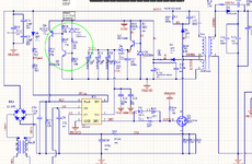
We are using the NCP1239P65 in a bog standard offline flyback as attached.
For the Fault pin, page 20 of the NCP1239 datasheet appears to suggest that the Fault pin draws in a
current of 1.2mA whenever the Fault pin is taken above 3V?. Would you say this is a correct interpretation
of the datasheet?

NCP1239 datasheet:
 

Attachments

  • NCP1239_latch pin current_qu.png
    NCP1239_latch pin current_qu.png
    156.8 KB · Views: 9
Hi,

I expect the 1.2mA to be the nominal current that needs to be applied to the FAULT pin.
So, in order to SAFELY activate the OVP function I´d apply "1.2mA PLUS SOME MARGIN"

Let´s say your external circuit activates at about 36V.
Let the voltage across CE of Q4 be 0.5V
so the current through R32 is (36V - 0.5V - 3V) / 27k = 1.20mA
The extra current through R23 is 3V / 22k = 0.14mA
leaves a pin current of only 1.06mA

In my eyes not a safe level to activate OVP.

***
The max pin voltage is 5.5V ... thus you may apply (5.5V - 1.35V) / 1.35kOhm = 3.07mA (nom)

--> I see no problem in driving the PIN with 1.5mA...2.0mA (at least 20% margin)
If you still want to protect the pin you could add an external 4.7V zener.

****
Disclaimer: I did not read the complete datasheet. Thus I may have missed some informations.

Klaus
 
Wonder why are you using a zener, 5 resistors and 2 transistors where the datasheet application uses a zener and an optional series resistor for OVP fault detection?

Datasheet says:
To reach the upper threshold, the external pull-up current has to be higher than the pull-down capability of the clamp, i.e. 1.2 mA.
Unfortunately there's no maximum rating for current into fault pin, you may want to ask Onsemi for a specification.
 
Can't make sense of figure 39...
If there really is a 1.35V zener on that node, then it's impossible for the OVP comparator to ever trip (threshold is 3.0V nominal)
I think that Rfault(clamp) must actually be in series with the Vfault(clamp) zener, rather than in series with the Fault pin.
 

LaTeX Commands Quick-Menu:

Similar threads

Part and Inventory Search

Welcome to EDABoard.com

Sponsor

Back
Top