Welcome to our site! EDAboard.com is an international Electronics Discussion Forum focused on EDA software, circuits, schematics, books, theory, papers, asic, pld, 8051, DSP, Network, RF, Analog Design, PCB, Service Manuals... and a whole lot more! To participate you need to register. Registration is free. Click here to register now.
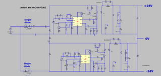
Well, it's a pretty crazy design and not very efficient or cost effective.
1. It uses half wave rectification at the input - why?
2. It duplicates all the components.
Suggestions: use a bridge rectifier at the input,
remove all the bottom half of the schematic,
use a different transformer and rectifiers to produce the positive and negative outputs,
add some voltage feedback to regulate the output voltage.
Also note it is difficult to provide the VCC to the ICs, particularly on the lower IC. You can't share VCC lines!
Thanks, its two half waves...so kind of "full wave"...also, you only go through one diode at a time ...not two diodes in series like in a full wave bridge, which mean wasted power.
Regulation for each of the output rails will be very tight, unlike a two coil secondary on a single flyback where there will be coupling issues.....and the rails may wander apart.
It does duplicate...but that means for a 75W offline flyback, you now need no heatsinks on the diodes or fets...unlike a single 75W flyback where it'd be adviseable to heatdsink the semi's.
If the output power was say 180W....you could use the 2 flybacks as shown (wit a bit of variation of components etc).......and this would be less custom magnetics than eg a two transistor forward.......2 tran forward, ayk, needs custom transformer, custom output inductor, and custom high side drive transformer....as well as two fets on primary and two fets on secondary.
Ayk, 180w would usually need a PFC, but not always....in any case, the same method as shown could be used with dual PFCs.
You didn't mention the load before but I would still raise the same concerns. Uneven loads on the outputs would also cause asymmetric loading of the AC input and that might cause other problems.
At the very least I would use a bridge rectifier and two identical circuits with one having its output rectifier/cap reversed.
This site uses cookies to help personalise content, tailor your experience and to keep you logged in if you register.
By continuing to use this site, you are consenting to our use of cookies.