piotr_jan
Junior Member level 2

My client had ordered a windows visualisation program fed by STM32 controller board. I have not been programing windows apps for many years, and decided to make a simple O-Scope & function generator using Nucleo446RE board.
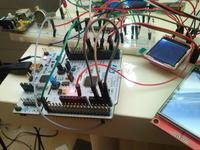
DAC output connected directly to the ADC input
User interface is ugly - but I enjoyed doing this project and I probably I will go ahead with it in the future, so comments are appreciated") .
.
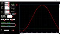
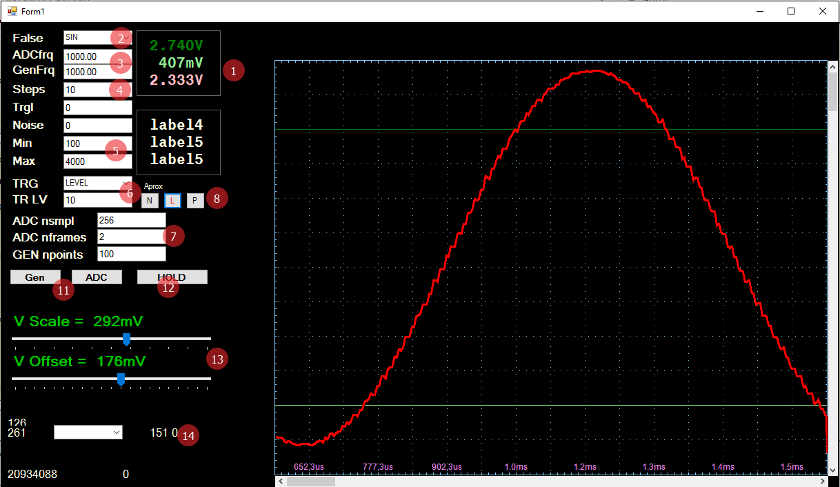
1. Measured Voltages - green lines are cursors
2. Function to generate
3. Frequencies in Hz. Input should be in time units, but I did not have enough time to change it.
4. Nsteps - number of steps for function generator
5. Min / Max - min & max voltage of the generated sisgnal (in 12 bit DAC units) Should be in V / mV but same as p3
6. Trigger - level in ADC units (8 bit) and the signal level / slope
7. ADCnsampl - how many samples are taken in one ADCfreq period
7. ADCframes - how many frames are actually transferred to the PC
7. GENnpoints - size of the function generator table
8. Approximation method N- none L - linear P -polynomial
11. It send the current settings to the Nucleo board (both do the same)
12 Hold - hold button
13. Y scale and position.
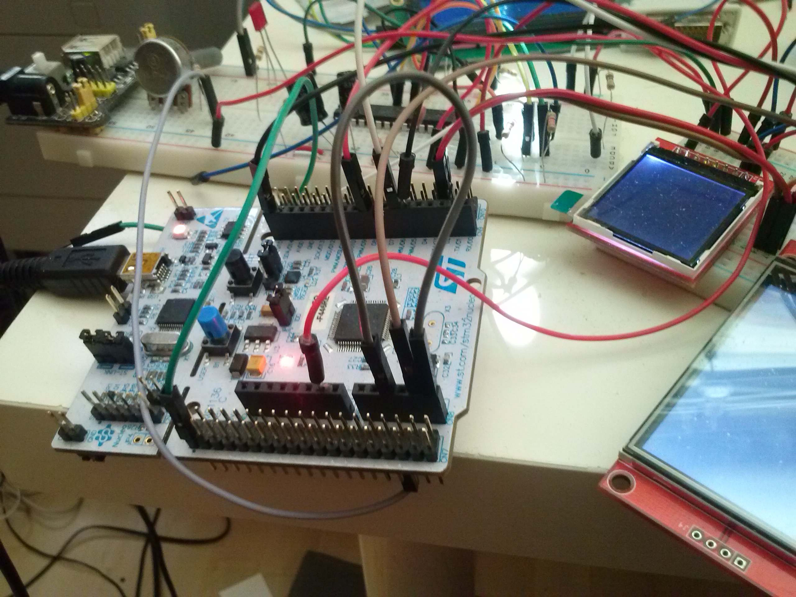
DAC output connected directly to the ADC input
User interface is ugly - but I enjoyed doing this project and I probably I will go ahead with it in the future, so comments are appreciated
.
1. Measured Voltages - green lines are cursors
2. Function to generate
3. Frequencies in Hz. Input should be in time units, but I did not have enough time to change it.
4. Nsteps - number of steps for function generator
5. Min / Max - min & max voltage of the generated sisgnal (in 12 bit DAC units) Should be in V / mV but same as p3
6. Trigger - level in ADC units (8 bit) and the signal level / slope
7. ADCnsampl - how many samples are taken in one ADCfreq period
7. ADCframes - how many frames are actually transferred to the PC
7. GENnpoints - size of the function generator table
8. Approximation method N- none L - linear P -polynomial
11. It send the current settings to the Nucleo board (both do the same)
12 Hold - hold button
13. Y scale and position.