Continue to Site

Welcome to EDAboard.com

Welcome to our site! EDAboard.com is an international Electronics Discussion Forum focused on EDA software, circuits, schematics, books, theory, papers, asic, pld, 8051, DSP, Network, RF, Analog Design, PCB, Service Manuals... and a whole lot more! To participate you need to register. Registration is free. Click here to register now.

NTC causing undervoltage shutdown at low mains

cupoftea

Advanced Member level 5
Joined
Jun 13, 2021
Messages
2,922
Helped
59
Reputation
118
Reaction score
134
Trophy points
63
Activity points
15,493
Hi,
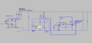
We are doing 130W Two Transistor forward. It comes after a three diode rectifier of
three phase mains, 100-265VAC.
We don't have PFC, so have a 220uF el cap after the rect, as you'd expect.
Before that, there is a 50 Ohm NTC. The problem is that at startup, it takes
2.5 seconds for the supply to get stabilised due to it dropping out repeatedly till the NTC
warms up. (this is likely to be worse at zero degc ambeint)

Similarly, if the supply goes to no load...then suddenly to full load, then obviously the NTC has cooled,
and so we get the 2.5 seconds of the supply repeatedly dropping out before it stabilises.

Our application cannot tolerate this.

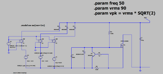
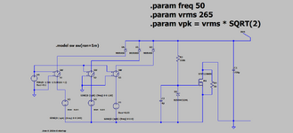
The NTC is 50 Ohms because of the spec of up to 265VAC input. However, some customers only want it
for 115VAC. Therefore, for these customers, I believe we should make the NTC = [130V*SQRT(2)] / (373V/50R) Ohms
= 24 ohms.
Would you say this is the best/cheapest solution?

(Inrush relay and its isolated supply would stress the budget.)

But am pondering a low side "MOSFET_with_sense resistor and NPN gate pull down" circuit aswell...perhaps combining this with say a 4R7 NTC .
Having said that, i dont think FETs SOA is really up to it in most cases.....and would rather do it with a nice rugged IGBT.
 
Last edited:
Hi,

your NTC type does not fit your current consumption.

Either design the circuit correctly or use an different circuit.

Klaus
 
50 ohms - where do you dream up these values - put 5 in //

or find a 10 ohm one
Thnaks, but the circuit does work fine once the NTC has warmed.
We need high ohms to really limit inrush, so if many devices turn on at the same time, then we dont get massive total inrush.
Whats wrong with NPN clamped FET as attached?
 

Attachments

  • CIN POST BRIDGE_inrush.zip
    1.3 KB · Views: 31
  • INRUSH 3 PHASE.png
    INRUSH 3 PHASE.png
    67.8 KB · Views: 36
Last edited:
50 ohms - where do you dream up these values - put 5 in //

or find a 10 ohm one
If I understand the problem right, then it´s on start up and on no load conditions.
(so not at the 130W load ... thus these 130W are not valid for the problem)

If so replacing a 50 Ohms NTC with a 5 Ohms NTC would be even worse for warming up, since it produces less heat at the same (no load) current.
On the other hand the 5 Ohms NTC may cause less voltage drop at no load conditions (even when cold).

As already written ... it needs proper design / calculation.... for all conditions from no load to full load, from minimum to maximum input voltage, from minimum to maximum ambient temperature. Capacitor size, thermal capacity of NTC...

Klaus
 
10 ohms limits the mains surge to 23Apk at instant of turn on ( worst case ) and allows the psu to operate at no load

at full load the NTC's should warm pretty fast and lower their R ( single phase 230Vac would be 1 amp rms ) = 10 watts initially - i.e. NTC R would fall rapidly.
 
OK thanks, the point is we cant use a 50R NTC, the NPN clamped FET does the job, is there any reason why it would be considered dodgy?
As long as FET SOA not violated then we shoudl be ok i would have thought. But we would prefer it with an IGBT.
Have you ever done one with an IGBT?

The trouble is that most FETs have really low SOA...

At 200v your allowed only 3A for 1ms or so...this is too low.

IGBTs are equally poor..
--- Updated ---

..then there's the delayed fet inrush.
But if the mains was jerking on and off, then
maybe the fet could get caught in linear mode
and let out the magic smoke.
 

Attachments

  • delayed fet.png
    delayed fet.png
    65.2 KB · Views: 31
  • delayed fet.zip
    1.2 KB · Views: 37
Last edited:
:unsure: ..not even taking out the calculator my pure gut feeling tells me that 50 ohm ntc and >120w psu will not walk together down the road for a perfect marriage.. I think i see typically like eg. dual 4r7 ntc inrush current limiter ntc's with supplies in that caliber (like above Easy peasy already calculated 10ohms or 5 and 5) in many commecial circuits..

Depending on powersupply input impedance, start up behavior, surgelimiter ntc's temperature-resistance curve, et cetera, i've seen it's possible for one to see such phenomenon Klaus described that the problem gets worse with lower values..however (still without calculator or anything more scientific than the experience gained from examining and repairing a sh17load of various powersupplies) i'm quite positive that going down with resistance may help here..i would set out a test to see what happens with 10ohm ntc's..

But..i think 2.5sec is quite a long time for the circuit to settle..have you been able to comfirm what exactly and in which order something is happenin there in the circuit during that 2.5 sec..? My assumption circuit-vise is the basic order in the circuit; Input, cmi/emi filter, ntc, rectifier, capacitor..it really takes no time to charge the cap through the 50ohm.. so just maybe there is a time constant based problem in psu controller start circuit? (just giving out some ideas..) ..like think eg. the old uc384x..It's Vcc cap has to be big enough to supply the controller until Vaux goes up..but at the same time the 'kickstart' resistor chain vs. cap value must not hover the Vcc around with high time constant..

Hope You will sort it out eventually..!
 
Thanks,
The attached is a circuit to bypass an NTC after the inrush event has happened.
However, even though the circuit is shown working here...this circuit is very bad.
The SOA of the Bypass FET is very poor. With some surge in the mains then this FET could end
up outside of its SOA....and so it must be replaced by a relay.
Would you agree that inrush bypass is the territory of relays, and FETs are simply
out of their depth here?

There is a saying in electronics "only a fool bypasses an offline inrush resistor with a FET or IGBT"...do you agree with it?
(LTspice and PNG attached)

Even thyristors are no good with offline inrush resistor bypass, because of their high dv/dt turn on problems.

Either an NTC is used alone...or a relay is used to bypass an NTC or inrush resistor. For offline, there is no other reliable method...do you agree?

Its the case of mains jolting on and off unevenly that could
end you up with a bypass FET getting "SOA killed"
 

Attachments

  • Inrush bypass FET.png
    Inrush bypass FET.png
    59 KB · Views: 36
  • inrush bypass FET.zip
    2.3 KB · Views: 33
Last edited:
The SOA of the Bypass FET is very poor
this is because many MOSFETs (generally: transistors) are considered for switching applications. Look for a MOSFET for linear operation, often they have a big package with heatsink tab.

****
SOA:
the main job of the NTC (or other inrush limiter) is to limit the current into the bulk capacitor at power on situations.
Ignoring other currents .. the energy stored in the capacitor is 0.5 x C x V x V.
The same energy has to be dissipated by a linearely operating limiter. Independent of type, resistance, voltage, current, time....

This is what your limiter device (SOA) needs to handle.

But the problem is the extra current.
It might be a faulty short circuit ... or it might be the expectable current to drive the load.
* to limit the "current by the load", I recommend to include a delayed soft start of the SMPS circuit. Maybe the delay is controlled by the limiter circuit (In a way the SMPS starts only after the limiter has become fully ON)
* to care about faulty currents .. is a bit more tricky. Here the NTC has it´s advantage, because due to it´s thermal behaviour it is rugged and thus a simple fuse may be used.
Other current limiting circuits dissipate a lot of heat ... and in one applicartion I used the temperature of the limiting element to decide a "fault condition". (Either too high current or too long time...). Still needs careful design of: power dissipation, timing, heat capacity...

Klaus
 

LaTeX Commands Quick-Menu:

Similar threads

Part and Inventory Search

Welcome to EDABoard.com

Sponsor

Back
Top