gres
Full Member level 4

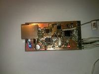
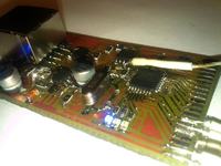
it’s a universal driver with communication via RS-485. you can call it an modem.
It consist those sections:
- power
- control
- conversion of RS-232 protocole in to RS-485
- memory
description:
heart of the system is 8 bits microcontroller ATMEGA8 clocked by 12MHz clock. Board has dimensions 65x35mm.
Power section consist LM78L05 + transistor that allow to get highest performance of stabilizer, power indicator light – LED, filtering elements RC and secure diodes against overvoltage. Power is +5V with performance about 800mA. In next version of this driver, rectify and zenner diode will be exchange by transil 18V
Driver section consist microcontroller ATMEGA8, 12MHz clock, 3 LED light indicators, output ports and power rail +5V at right side of PCB.
Communication section is RJ-45 slot, conventer 232-485-SN75176 ( similar to MAX485)
Memory section is EEPROM 1kB –AT24C08 plugged by i2c.
Designing
Board were designed in Express PCB ( freeware and very useful). Path thickness is 0,2 – 0,76mm)
I decided to make the board as a surface mount. As I’m going to make a lot of this drivers, I decided that making each board with chronic montage will take too much time. Thanks to surface montage I was able to minimalism dimensions of the board. I tried put paths this way to keep all elements tight together.
Because montage is one side, I need to used jumpers. As a jumpers I used “resistors” 0,125W in 1206 casing – there are 8 of them in the casing.
More in formations at https://www.elektroda.pl/rtvforum/topic1575906.html


