Continue to Site

Welcome to EDAboard.com

Welcome to our site! EDAboard.com is an international Electronics Discussion Forum focused on EDA software, circuits, schematics, books, theory, papers, asic, pld, 8051, DSP, Network, RF, Analog Design, PCB, Service Manuals... and a whole lot more! To participate you need to register. Registration is free. Click here to register now.

Non-sinusoidal supply current will damage petrol generator?

cupoftea

Advanced Member level 6
Joined
Jun 13, 2021
Messages
3,103
Helped
62
Reputation
124
Reaction score
139
Trophy points
63
Visit site
Activity points
16,154
Hi,
We have 240W isolated loads (up to eight at a time) running ultimately from a 3kW, 230vac Petrol generator.
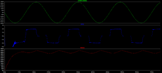
The current supplied by the generator is not sinusoidal, but its as in the attached. Do you think
this will wear out the gennerator's bearings and overheat it?

(Specially if say eight of these 240W loads are being supplied at the same time?)

230VAC petrol generator:

The generator is fed to a Boost PFC then 240 W Two transistor forward. (up to eight of these, ie eight 240W Boost/2TF's)

The load often turns from full on to full off with a 5 second period (5 seconds ON, 5 seconds OFF).
The load switching ON or OFF is extremely sudden
(approx within 1us)

As such, we didn't do a proper boost PFC, we instead did a Fast Boost converter otherwise the boost PFC
output fell too low. (it dropped out following a no-load-to-full-load transient). Hence the non sinusoidal supply current.

In the attached , green is the generator output voltage (230VAC). Blue is the generator's supplied current.
Red is the Boost "PFC" output voltage. (obviously its not really truly PFC'ing)
 

Attachments

  • Current drawn from 240VAC petrol generator.png
    Current drawn from 240VAC petrol generator.png
    54.1 KB · Views: 35
Last edited:
The loads determine the current waveshape, mostly, if the inverter output voltage is the " quasi - sine " i.e. stepped square wave about 200V peak then this will influence the current drawn by the loads, however,

if it is sine wave voltage out the loads will entirely determine the current waveshape - up to the current limit of the inverter.

How is it you think the bearings might be affected ?
 
Thanks, there is no inverter here....just that current coming out of the generator, and going to the loads.
The current to only one load is shown, if there's eight than it'll just be 8x what you see there, because there'll all draw the same current from the generator, and "In phase" with each other.

I had always thought a generator would run smoother if supplying a sinusoidal current in phase with its voltage?

(A motor is like a generator in reverse, and they always say eg a sinusoidal BLDC runs smoother than a trapezoidal one.)
 
Last edited:
We have 240W isolated loads (up to eight at a time) running ultimately from a 3kW, 230vac Petrol generator.
There are two important electrical parameters.
* 3kW is for the motor ...
* and there should be an kVA rating for the generator ... or at least an Amperage rating.
both need to be fulfilled by your power supply

The generator is fed to a Boost PFC then 240 W
before you wrote there are 8 loads. So are there 8 PFCs or only one. Do all loads switch ON/OFF synchronously or randomly independent?

In the attached , green is the generator output voltage (230VAC). Blue is the generator's supplied current.
Red is the Boost "PFC" output voltage. (obviously its not really truly PFC'ing)
I wonder that the generator voltage is that sinusoidal .. with that non-sinusoidal current. Is both voltage and current from simultaneous sampling?

****
Do you think
this will wear out the gennerator's bearings and overheat it?
The motor obviously is a combustion engine ... 4 stroke, one cylinder, thus one explosion every 2 revolutions. This is where "sideways force" is put on the bearings of the motor. I expect this explosion forces much higher than what your load will cause ..
Additionally the load current causes torque. The torque is not being transferred with the bearing. The bearings get no stress with torque.
It´s the shaft that has to stand the torque and the torque waveform.

I´m not saying that the whole motor-generator is suitable for your load. But I don´t think that bearings in motor or generator are stressed by the waveform of the electrical current.

***
If you are the designer of the (non) PFC: then I recommend to design it a bit more intelligent. I mean you see the output current of the PFC (or even better: you have a signal that gives the "load ON/OFF" signal.) According this signal switch the PFC (duty cycle) ...in a way that you don´t rely on the slow acting feedback of the PFC output capacitor voltage. This way you get a fast change in PFC duty cycle .. resulting in fast switching from low current sine waveform to high current sine waveform ... without undershot or overshot of the PFC output voltage.

Klaus
 
before you wrote there are 8 loads. So are there 8 PFCs or only one. Do all loads switch ON/OFF synchronously or randomly independent?
Thanks, anything from one to eight loads, and they will switch together. Yes, 8 "PFCs"......I use the "PFC" term loosely because
its more like a fast boost converter than a true Boost PFC.

wonder that the generator voltage is that sinusoidal .. with that non-sinusoidal current. Is both voltage and current from simultaneous sampling?
Thanks, thats the LTspice waveforms...i assume a sinusoidal generator voltage.
--- Updated ---

If you are the designer of the (non) PFC: then I recommend to design it a bit more intelligent. I mean you see the output current of the PFC (or even better: you have a signal that gives the "load ON/OFF" signal.) According this signal switch the PFC (duty cycle) ...in a way that you don´t rely on the slow acting feedback of the PFC output capacitor voltage. This way you get a fast change in PFC duty cycle .. resulting in fast switching from low current sine waveform to high current sine waveform ... without undershot or overshot of the PFC output voltage.
Thanks, yes i believe the best way to do this would be to use a micro to do the PFC and program it optimally....however, we just want to hack it with a cheap BCM PFC chip.......so what we have is a comparator (+ some hysteresis) looking at "pfc" vout, and then the comparator switches it to max power throughput.....(ie, we hacked the "VIN_SENSE" pin so that the BCM chip "thinks" its at mains peak for most of the mains cycle). Also, the comparator switches the voltage on the error amp output COMP pin from min to max, depending on whether the PFC vout is above or below the thresholds.
This does the job, so i think we will leave it as its cheap......we dont need true "PFC" as its just a lone generator out in a field.

The good thing about a BCM PFC chip is that they have that feature where they reduce the peak current threshold when near the mains zero cross...and we need that as it rings like mad near the zero cross if we dont have that.

So basically, we just hacked up a cheapo BCM PFC chip as it seems to do the job, but we worried about the generator getting somehow damaged as its not a nice sine current.
 
Last edited:
full mechanical ( derived from electrical ) load places the most stress on the bearings. The teeny tiny mech pulsations from any pulsing current are are several orders of magnitude lower - due to flywheel effect of the mech setup.
 
b不会,这跟电流强度有关,也需要判断发电机的承载极限值

[translated by Google]
No, this is related to the current intensity, and it is also necessary to determine the load limit of the generator
 
Last edited by a moderator:
It is not that the current supplied by the generator is not sinusoidal, its that the load consumes non-sinusoidal current.
does the pfc controller IC multiplies the voltage feedback to scale the power demand? if so than what is the issue with doing a simple speed-up circuit to the voltage feedback?


I understand that you are considering the mechanical stresses of this high pulsating current but also take into account what will be the effect of generator output voltage of this very high pulsating current.
 
I'd delete the term "PFC" in subsequent discussion. The shown current waveform has nothing to do with PFC, as already conceded.

An AC generator has relevant source impedance (mostly inductive), respectively we can expect a distorted voltage waveform with the assumed current waveform. Asynchronous generators might involve shunt capacitors.
 
Thanks, in the distortion, what would you expect the peak voltage to be ?
Also, how non-sinusoidal do you believe it will be?
Is this idea of speeding up the "PFC" thus going to be a non-runner?
The high di/dt of the current waveform is obviously going to put voltage spikes i agree into the generators voltage output, due to its inductive nature.

It now seems to me that we are going to have to slow the "PFC" back down and use a big output capacitor bank in it.

What would happen to the generator voltage if we had 3000W's worth of non-PFC'd loads?.....eg, loads that just had a rectifier bridge at the input, going into a smoothing capacitor?

So is it a pre-requisite that one must have "proper" PFC for any load taken from such a small (3kW) generator.?
 
Last edited:
What would I expect the peak voltage to be? no one can tell you that, only experiments. it depends on how much of an inductor the generator really is.
What would happen if you had 3000Ws worth of non-PFC'd load? why even go there? if it breaks in 10 days its ok? if it breaks in 1000 days its ok? just do a good PFC design and be on the safe side.

Look at UCC28070 - when load step occurs the VSENSE drops down and when its too low there is a 100uA current source pushing charge to voltage feedback capacitor, rising its feedback voltage rapidly. You could implement such a mechanism very easily.
also make sure to implement a similar (yet negative in nature) mechanism for when VSENSE rises too high.
 
Thanks, they should really say in the advert (in the top post) that it can only supply loads with a power factor corrector, i am amazed it doesnt say this.....PFC isnt mandated below 75W, and its entirely conceivable that a customer could plug say thirty 70W , non-PFC'd loads into this generator. When "Joe Bloggs" buys an AC generator, he just thinks that its like a portable mains supply....its obviously nothing remotely like that.

Its all starting to make sense now.
Years ago a company who made non-PFCd amplifiers to plug into the mains
suddenly wanted some PFC'd ones....seemed strange as everything was done as cheap as poss.
But I see now that the point is that when you are running off one of these wee little
generators, you absolutely must do PFC (and properly).

It seems that to use this AC generator, what you really need to do is put a Power Factor corrector after it.....make that give a 400VDC rail...and give that to an inverter which can give a sinusoidal (230VAC) voltage output no matter what current is drawn from it. I think the advert should say...."must also be used with PFC then inverter"....but then again.....if you go ...AC PETROL GENERATOR ---> BOOST PFC --->400VDC.......then why follow that with an inverter?...why not just use the 400VDC as your distribution bus and power your loads from that? Just have sufficient DC fusing.

UCC28070...yes thanks....I ordered 4 of these from a well known disty some years ago for a project.
And all of them were either physically damaged or ESD damaged. The entire project got cancelled
because the whole board had been done for UCC28070 and they didn't want to change it.
____---____----____
The following is a petrol generator into an inverter, and it appears that this is needed if generally available mains-connectable loads are to be connected. So it appears a straightforward generator by itself, cannot be connected to a load , unless of course its purely resistive.


__----__---
In the following they are thorough enough to say that its not suitable for LED lights or general digital equipment. ( of course i assume ot would be if a PFC stage was used)

___---____---___---_
The PG8300A of the top post doesnt seem to have an inverter in with it but is said to be able to supply sensitive electronics loads such as laptops, TVs etc. So how is it this generator can supply this stuff but others need an inverter to do that? Also, the spec says it has an "automatic voltage regulator" in with it, but do you know what this is?....might it actually be an inverter?

PG8300A...

----___---__---__
I asked the question to another AC petrol generator vendor, about whether the generator output needed to be power factor corrected or not , and was told "whats power factor corrected?". I then asked what the waveform was coming out of the generator and they said, that they didnt know, but if i wanted a sine wave output then i had to buy an inverter aswell..........presumably they mean an inverter with a PFC at its front end, but i didnt ask that, because they didnt know what a PFC was.
 
Last edited:

LaTeX Commands Quick-Menu:

Similar threads

Part and Inventory Search

Welcome to EDABoard.com

Sponsor

Back
Top