Continue to Site

Welcome to EDAboard.com

Welcome to our site! EDAboard.com is an international Electronics Discussion Forum focused on EDA software, circuits, schematics, books, theory, papers, asic, pld, 8051, DSP, Network, RF, Analog Design, PCB, Service Manuals... and a whole lot more! To participate you need to register. Registration is free. Click here to register now.

non-interlaced RGB >> svideo design

Status
Not open for further replies.

VSMVDD

Banned
Advanced Member level 2
Joined
Jun 12, 2005
Messages
643
Helped
92
Reputation
184
Reaction score
34
Trophy points
1,308
Location
scotland uk
Activity points
0
interlaced rgb

edited

see lower postings

big thanks to all :D
 

rgb to svdo

8_1169785682.jpg


Don't donate points to me
 

proteus v7 rgb

Thanks budhy m8

Thats a Large Spliff and a bottle of beer in the dam :D i owe you

Added after 1 hours 28 minutes:


Here is a copy of what i used it for and made the pcb
over the last hour or so ....

**broken link removed**


it is an advanced atari computer series
non interlaced rgb to svideo channelised output

rather than the crap 1377p

i used its big brother

what a picture difference !!!!

take a look if you need a similar project

the pcb foil is there i exported and seems the gaps and pads dont wash or fill
so a good clean pcb from photo etch or press and peal

if you used it post how you got on

ill put up a site with this project once
i add the atari connections pictures
and install texts


im sure youll see how to connect it

maybe an insult to post it hehe however its here now....
as just a mark1 {may have a flaw } but im confident 9.996/10

youll need proteus or a demo of it to open the main designs
although the schematics and foils are there as jpg files also


dont forget its not just for atari computers many devices use this method
of rgb output and there is poor support now
for conversion form older to new style tv/lcd inputs

also allows connection to a pc tv card or capture cards

...


rgb non interlaced

added an smd mc13077 pcb layout
incase you can only get this part type localy
 

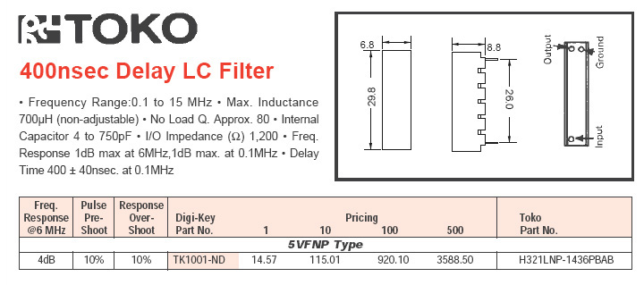
mc13077 luma delay

corrected the component's layouts it appears i had the pins
on the delay line and bpf the wrong way round

also it looks like the toko range i made some time ago
for vsmlibs collection also have the pins placed incorrectly


i am planning a big update to vsmlibs archive as soon v7 is avalible

you see this is what happens when people never give any debug email

i need feedback for vsmlibs im only human and mistakes occur


debug vsmlibs post here please

vsmlibs@yahoo.co.uk


i dont mind doing the work
but ffs tell me im wrong dont just sit there and say FA....
 

Status
Not open for further replies.

Similar threads

Part and Inventory Search

Welcome to EDABoard.com

Sponsor

Back
Top