cupoftea
Advanced Member level 6

Hi,
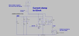
Please imagine you have been given a crowded PCB layout which comprises the attached Current Clamp circuit. (jpeg and LTspice) The sense resistor is some 5cm away from the opamp, and in the short given time that you have, bringing that nearer to the opamp will not be possible.
As such, I assume that you would want to be sure that as much as possible, the sense resistor gets “diff pair” routed back to the opamp?
Also, the schematic shows six ringed noise mitigation capacitors. Supposing that you can only use 1 of them. Which one would you choose?
Now say you are allowed two of them….which two would you choose?
(BTW, the 1.25V reference is also some 6cm away from the opamp.)
Also, C2 looks like a potential problem....it is pretty well direct from opamp output to rail, which is a no-can-do with many opamps....would you agree?

