Continue to Site

Welcome to EDAboard.com

Welcome to our site! EDAboard.com is an international Electronics Discussion Forum focused on EDA software, circuits, schematics, books, theory, papers, asic, pld, 8051, DSP, Network, RF, Analog Design, PCB, Service Manuals... and a whole lot more! To participate you need to register. Registration is free. Click here to register now.

Noise Before and After Resistor

Status
Not open for further replies.

umery2k75

Advanced Member level 1
Joined
Apr 19, 2006
Messages
434
Helped
42
Reputation
82
Reaction score
16
Trophy points
1,298
Location
Pakistan
Activity points
5,748


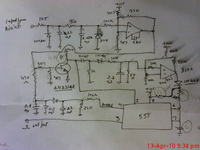
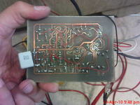
Here is the circuit. There is a 1.5KOhm resistor for the magnetic pickup point. It would be getting pulses from the generator much like a sinusoid, but distorted. So before testing it on the machine. I decided to drive it through a sinusoid generator.
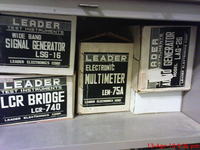


I had this LEADER Audio generator. It's not in the box. It must be misplaced somewhere in the home. So I hooked up the audio frequency from the computer. A sinusoid at 1Khz around 1-2volt pk-pk.

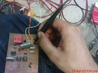
Here is the setup
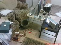


When I use the probe on 1K5 resistor directly coming from the cable. I get these types of distorted wave.
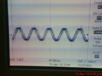
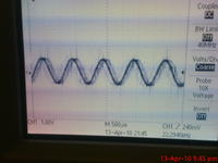
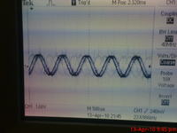
After the resistor, I'm getting a very clean wave form. What the resistor is doing. Is it keeping the noise away. It might be a very faint noise.I never thought of resistor as noise remover before?
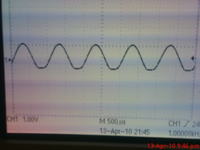
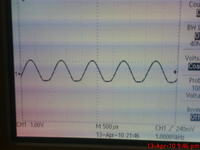

Here is the circuit.
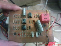


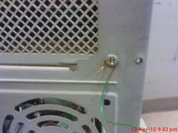
I thought maybe the Computer Body is generating some noise. I decided to Earth the body. I didn't have Earth over here. So I used the jumper from the neutral receptacle
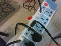


and I tie it to the computer body, like this. Still the noise is present. I'm able to see noise on the Power Supply also. I don't know why. If I alone check the power supply. It gives a very clean DC output. But with all these system connected together. I'm getting noise. If resistor can eliminate such noise. Should I use let say a 1Ohm resistor in series with the 12V supply. So that noise will go away. Resistors seems to be working as a NOISE REJECTOR over here.
 

I think, everything is obvious. You have high frequency interferences, showing as spikes in the input waveform. The signal isn't
actually distorted, but it's not clearly triggered due to the interferences.

You should know better, what the interfering signals are, looks like SMPS, UPS or VFD borne. The problem is, that these interferences
also spread across the ground connections, so it may be difficult to make a correct oscilloscope measurement of any circuit
node in this case. I can't see from your photos, if you're using a short probe ground clip as required to minimize measurement artefacts.

Assuming, that the measurement ground reference is realiable, the result can be simply explained with the low-pass filtering of the
probed RC circuit. But considering the previous mentioned problem of a correct ground reference, the situation may be more complex.

Some points haven't been mentioned yet, e.g. selected oscilloscope bandwidth.

In any case, it's an all-days measurement situation, at least if you are dealing with power electronics respectively low level
signals even in an electrically "clean" enviroment. It may be difficult to indentify the exact interference source, but the interfering
signals exist, surely in your measurement and most likely also at the circuit input. You have to take it into account.
 

    umery2k75

    Points: 2
    Helpful Answer Positive Rating
Status
Not open for further replies.

Similar threads

Part and Inventory Search

Welcome to EDABoard.com

Sponsor

Back
Top