Vermes
Advanced Member level 4

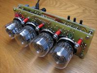
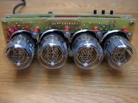
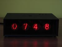
It is a 24-hours clock, which displays hours and minutes, with alarm clock, sustaining in the event of a power outage, with possibility of turning off the display of the left zero for hours and “rewinding” all the numbers in the lamps every hour. It was designed for LC-513, but the whole structure is so well thought out, that it is relatively easy to customize it for any other lamps.
Construction
The construction is typical. Multiplexed lamps were used, so that Attiny2313V may control the whole.

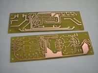
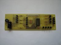
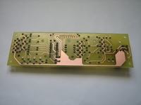
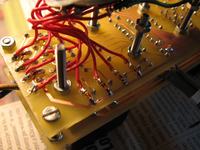
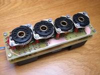
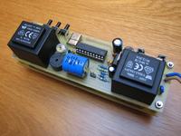
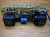
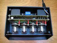
Because of the often occurring problems with activating the transformer for powering the lamps, this part was built in an other way. For making the high voltage for the lamps, second transformer TR2 was used, connected by secondary windings to the secondary windings of TR1. Transistors were used to connect them to a cheap decoder 4028. When broken, there would not be necessary to change the whole system, but only a single transistor. The construction was placed on two plates: the clock on one of them and the driver for lamps on the second one. Stands of the lamps were screwed to the driver. P1 is a simple piezo plate without generator. An accumulator is used to maintain the power supply, it should last for more than two days.
The program and the clock settings
The control program for the microcontroller was written in C under WinAVR in two versions. The second version has all the features mentioned in the introduction, the first version is just a simple clock without alarm, in which there are only buttons S1 and S2 to set the hours and minutes.
The clock is equipped with three buttons to set time and alarm and optional fourth button (S4 [MODE] – not in this model), which can switch between displaying the time in HH:MM and MM:SS. Longer holding S1 [TIME] allows to enter time setting mode. Button S2 [SET] changes the value displayed on the position of hours. Short pressing the [TIME] button moves to set minutes. Another pushing this button results in exiting time setting mode, while approving the settings and resetting the seconds.
Setting the alarm clock is done in the same way as setting the time, with the fact that we use the button S3 [ALARM] instead of the [TIME] to enter the setting mode and press [SET] to change the value. Enable/disable the alarm is done by briefly pressing the [SET] in the time display mode and is indicated by the extreme left dot glowing. The alarm turns off automatically after a minute, but of course it can be deactivated earlier by pressing any of the buttons briefly while it is heard.
To enable/disable displaying the left zero for hours, just briefly press the [ALARM] in the setting the time mode. The 'scroll' numbers function allows to minimize the effect of poisoning cathodes of numbers that do not glow for longer time and it automatically runs every hour.
Installation and possible changes
Zener diodes D3-13 on the plate of the driver should be mounted from the side of paths, because there is not too much space, and because of the high voltage, too decently placing components is not recommended. SMD or simple diodes with close-cut outputs may be used. The plates may be connected to each other by connectors or flexible cables.
The clock can be customized by any nixie lamps. Just make an additional third plate (e.g. universal plate screwed to the other ones), with attached lamps, and the whole clock can be positioned horizontally or vertically, depending on whether the lamps display numbers from above or the side of the bulb. When the lamps do not have dots, little neons with properly selected resistors may be used. In this model the transformer with the voltage of secondary winding 12V, slightly higher than TR1 (9V) was used, in order not to get too high voltage for the lamps with no load. In such combination the voltage under load decreases quite rapidly, in consequence of which obtaining a maximum current of 2-2,5mA at a voltage of 165-170V is real.
The clock do not have to be placed in a housing (it can be placed in KM-50 with red filter).
Note! The clock is powered directly from the power network and there are dangerous high voltages. Always work with care.


Link to original thread (useful attachments) – Zegar Nixie na LC-513