Vermes
Advanced Member level 4

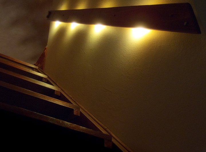
This device is a solution for night lighting of places such as stairs, corridor etc. It turns light on for the time of going up or down stairs and automatically turns off after time set when running autonomous (battery), making it independent of the access in a particular place of grid. The prototype lights stairs to the loft.
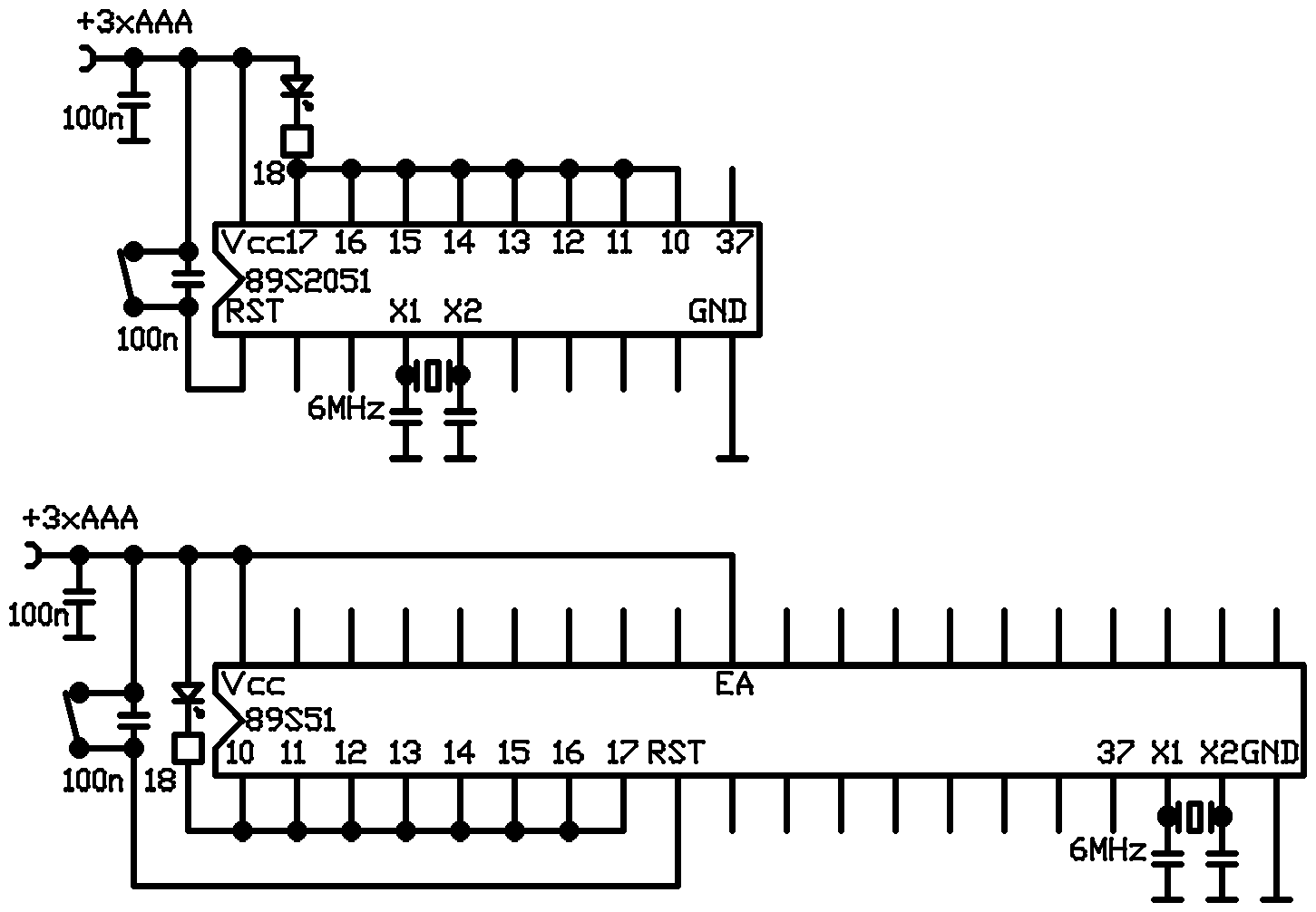
The system consists of:
- microprocessor '51 (Atmel) – ideological-mounting diagram shows the solutions for both large and small processors
- quartz 6MHz – noncritical value
- oscillators of capacitor (22pF or 4,7pF depends on the processor used)
- capacitors that block the power and reset (100nF – noncritical value
- resistor 18R that limits the current of LEDs to about 25mA (at power voltage of 4,5V)
The system is powered by three AAA cells, and the current consumption is about 30mA during operation and negligible during standby. Therefore, when several times a day used, a set of small sticks is enough for at least a year of work, big sticks (AA) – for three years.
The use of microprocessor allowed the effects: mild brightening, lighting for a set time and slow blackout. Times can be changed within a wide range by declaring the variables in the program: fadein (lighting time), time (runtime), fadeout (fading time). These times can be respectively about one second, minute and 30 seconds.
After the light cycle, the microprocessor goes into freeze mode and re-work is possible after its reset. Therefore, turning on the light is implemented on the showed schema by a button with reset and power, using which in the event of e.g. stairs, it is possible to duplicate in parallel (it is at the beginning and end of the railing in the picture).
The first port works for a common load to increase the current efficiency. The prototype device was powered by four white LEDs connected in parallel. If the 25mA current was too low, by field-effect transistor, receivers with higher power consumption can be driven. Note that the supply varies within wide limits, and therefore the current will change also. Therefore, the selection of resistance values for the raw power LEDs (without current driver) must be made at the maximum theoretical voltage (about 4,5V). If necessary, the system can be powered by four cells.
3.7 port changes its state at a frequency of about 3Hz and can be used as a indicator of work when controlled by a LED plugged to power through a resistor (about 1kR).
Some of the processors according to the catalogue note work only from 4V, and therefore not at voltages available of three batteries (3-4,5V), but in practice, at this frequency of quartz, it is able to cope even with the voltage of 2,8V.
The system was built without the PCB due to its simplicity and in prototype it was completely hidden under the railing seen in the picture.
Link to original thread (useful attachment) – Sterownik oświetlenia nocnego
