Terminator3
Advanced Member level 3

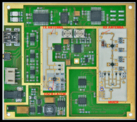
Hello All! I want to build simple oscillator as shown in this article:
**broken link removed**
1) Is it Colpitts oscillator using transistors parasitic capacity? (I read some tutorials from https://www.edaboard.com/threads/85698/ )
2) If it is, How do we know parasitic capacity of transistor. Where is the second "capacitor". Is it good idea to add some smd capacitors?
3) How to determine length L=... between transistor base and R1 welding point (Is it L=WaveLength/2, so we get phase shift of 180. Then transistor itself adds 180 and we get 360 phase shift for proper feedback?)
4) How i can mathematically determine microstrip line lenght and R1 parameters?
5) Can I use this scheme as low-power RF oscillator? How bad is it? Maybe other simple scheme without Dielectric Resonator exists?
6) Can i get RF signal before R1 using SMD or microstrip capacitor and connect it to some kind of antenna?
Thanks!


