joanjay
Newbie level 6

- Joined
- Nov 27, 2012
- Messages
- 11
- Helped
- 0
- Reputation
- 0
- Reaction score
- 0
- Trophy points
- 1,281
- Location
- Philippines
- Activity points
- 1,372


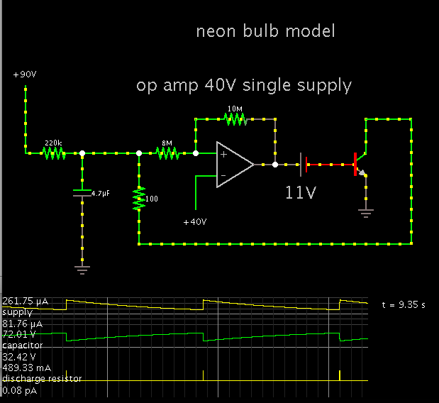
I found the figures above online.. I've been trying to regenerate the same simulation as in Fig.3. I need some help doing it. I have a few questions.
1) What are the values of R and C (fig.1/fig.2) to that will make a 10sec. flash rate?
2) What is the purpose of Rh in Fig.2 and what should be the value?
3) What do you mean by RON=1K and ROFF=10M in Fig.2?
Fig.2 includes a seemingly non-inverting Schmitt trigger circuit if the 8M resistor will be placed be placed just before Rh? My last question:
4) How will the computation given by the link below be affected by the 8M resistor?
http://hyperphysics.phy-astr.gsu.edu/HBASE/electronic/schmitt.html#c3
Neon bulb parameters: VON = 65 V; RON = 1k; ROFF = 10M; hysteresis = 55 V (the bulb remains on until the voltage across it drops below 10 V)