Continue to Site

Welcome to EDAboard.com

Welcome to our site! EDAboard.com is an international Electronics Discussion Forum focused on EDA software, circuits, schematics, books, theory, papers, asic, pld, 8051, DSP, Network, RF, Analog Design, PCB, Service Manuals... and a whole lot more! To participate you need to register. Registration is free. Click here to register now.

Need to upgrade it... help guys

Status
Not open for further replies.

aq_mishu

Full Member level 4
Full Member level 4
Joined
Jul 16, 2007
Messages
212
Helped
1
Reputation
2
Reaction score
1
Trophy points
1,298
Activity points
3,402
Guys,
I got this from a site... it is an inverter... i'll modify it using AVR for making the waveforms... modified square wave. and then the mosfets for powering up it from 24VDC-220VAC. Till this, i can work... but i am planning it to make a full auto emergency backup power... obviously for long time backup... kind of IPS/UPS. I call Instant Power Supply. This the inverter needs a charger for batts. I am planning to use the same transformer here to reduce cost. also the mosfets for rectification so that large current can be rectified. Thus can you tell me how??? I cant actually figure out any solution....

Mishu~
 

Attachments

  • modified_sine-wave_inverter-schematic_3422.png
    modified_sine-wave_inverter-schematic_3422.png
    106.3 KB · Views: 128

so that transformer is just a 50/60hz one ? ok
what your asking is if you apply 240VAC or 120VAC (depending what your AC supply is)
you want the mosfets in the circuit to do the rectifying for it ?

draw a half-wave rectifier (2 diodes), then try to imagine the mosfets doing the same
duty, except the mosfets are not self commuting, so your avr device with have to
switch them in synchronous to the wave form out of the transformer.

I said the mosfest are not self commuting, hmm but they can be...there is the intrinsic diode they all have, so i'm not sure the circuit can be that simple.....
anyway thats all i'll think of for now, and see what you come up with :|

cheers
 

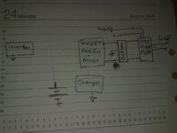
according to this block diagram, i need the charger will use the mosfet for rectification and will charge the battery bank when the mains is available. and when the mains is not available, then charger will go off, the inverter will produce AC. now can you guys finish the block diagram for me.. i mean i cant find out a path and my brain is getting jammed.


Mishu~
 

Status
Not open for further replies.

Part and Inventory Search

Welcome to EDABoard.com

Sponsor

Back
Top