remyatr
Newbie level 2

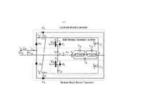
i would like to simulate the elecronic ballast circuit which shown below using simulink.There is an input buck boost powerfactor correction stage in the input and a resonant inverter stage is in the output stage which is used to drive the lamp.i would like to operate the buck boost convetrer in Dicontinuous Conductiion mode with a fixed frequency and the duty cycle is .5.The switching frequency is tken greater than resonant frequency.I Need to konow about how i can design the control circuit for this ballast ? and how i am able to simulate this ballast using simulink?
url=http://obrazki.elektroda.pl/81_1255498254.jpg]
 [/url]
url=http://obrazki.elektroda.pl/81_1255498254.jpg]
