Continue to Site

Welcome to EDAboard.com

Welcome to our site! EDAboard.com is an international Electronics Discussion Forum focused on EDA software, circuits, schematics, books, theory, papers, asic, pld, 8051, DSP, Network, RF, Analog Design, PCB, Service Manuals... and a whole lot more! To participate you need to register. Registration is free. Click here to register now.

Need help with single-phase full-wave rectifier

Status
Not open for further replies.

SPB

Newbie level 2
Newbie level 2
Joined
Mar 4, 2019
Messages
2
Helped
0
Reputation
0
Reaction score
0
Trophy points
1
Activity points
30
This is for a school lab.

My theoretical calculations are not matching the pspice simulations. I have attatched photos of the circuit constructed and simulated.

Circuit.JPG

Pspice simulation.JPG

With a peak input voltage of 169.7 and a primary inductance of 2000H and secondary inductance of 20H I'm getting an output voltage at Vs1 and Vs2 of 11.931 volts according to the simulation.

However, my predicted values according to my theoretical work are as follows:

Vp/Vs = sqrt(L1/L2)

Vs = Vp/sqrt(L1/L2)

Vs = 169.7/(sqrt(2000/20) = 16.97

So at the positive and negative half cycle for each Vs1 and Vs2 I should expect +16.97 and -16.97 respectively. Why am I getting 11.931 in the simulation?

Are my calculation incorrect? Or did I not edit the transformer correctly.

I edited the properties of the transformer as follows:
LP_VALUE - 2000H
LS1_VALUE - 20H
LS2 - VALUE - 20H

Is there something else I am missing?
 

I'm a bit new with this software but I think one of these are what you're asking for:


Code dot - [expand]
1
2
3
4
5
6
7
8
9
* source TEST2
X_TX1         N01326 0 N01860 0 N01906 XFRM_LIN/CT-SEC PARAMS:  LP_VALUE=2000H
+  LS1_VALUE=20H LS2_VALUE=20H COUPLING=.99 RP_VALUE=0.1 RS_VALUE=0.1
V_V2         N01316 0  
+SIN 0 169.706 60 0 0 0
R_R1         N01316 N01326  10 TC=0,0 
R_R2         0 N01864  3.1k TC=0,0 
D_D1         N01860 N01864 D1N4148 
D_D2         N01906 N01864 D1N4148


Or...


Code dot - [expand]
1
2
3
4
5
6
7
8
9
* 
* 
0 1405 0 
R1 1407 1406 10
R2 1954 1405 3.1k
D1 1955 1954 D1N4148
D2 2161 1954 D1N4148
TX1 1407 1405 1955 1405 2161 XFRM_LIN/CT-SEC
.END

 
Last edited by a moderator:

I edited the properties of the transformer as follows:
LP_VALUE - 2000H
LS1_VALUE - 20H
LS2 - VALUE - 20H

2000 Henries is a large value to make into a transformer. It has a choke effect at 60 Hz, and so presents large impedance to the power source.
Less current flows, the flux field is weaker. This affects the secondary output and could explain your low power reading.

4 Henries is a typical value found in the primary of transformers which are powered by house voltage.
 

Your calculation is correct: the coupling factor you used (0.99) can be neglected.

I think the scale of the graph you represent the output waveform is too wide. Try to plot the output waveform with a reduced scale (f.i. -20 to +20 V) and measure again the value.
Another thing: you may not have enough simulation point on the sinewave so you didn't catch its actual maximum (or minimum)
 

At 60Hz the secondary has an impedance of 1200 ohm, about 1/3 of the load resistance.
17V (3100/(3100+1200)) = 12.3V

You expected 16.97 V and got 11.93.
The 0.3V extra I estimated can be dropped in the actual coil resistances, which you set to 0.1 ohm (assuming I read your spice file correctly), the 10 ohm series resistor in the primary and in the forward drop of the diodes.

It looks like SPICE got the correct result.
Just because your calculation and someone else's calculation (i.e. SPICE in this case) aren't EXACTLY the same, doesn't mean they disagree, or that one (or both) are wrong.

It means that there is an understanding gap.
You know the truth when you fill in the understanding gap.
 

At 60Hz the secondary has an impedance of 1200 ohm, about 1/3 of the load resistance.
17V (3100/(3100+1200)) = 12.3V

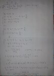
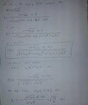
Unfortunately your calculation is not correct. I've got a rigorous mathematical derivation starting from the general case of mutual coupling.
Here is the results:

Pag. 1.jpg Pag. 2.jpg
 

@albbg: I've been around long enough to know that I've been right, and i've been wrong and i'll be right again and I'll be wrong again.
In this particular case, I intended to estimate the voltage across the resistor, but the spice graph is of the secondary coil. Another error.

@SPB: try BradtheRad's suggestion: rerun the simulation, this time with 10H and 0.1H instead of 2000H and 20H. Its not 4, as Brad suggests, but it is a lot closer to 4 that 2000.
Also, use albbg's suggestion to use more simulation points. Use the same time scale, but up the data points by a factor of 10. This will lengthen the simulation time by a factor of 10 (at least). But it looks like the simulation you posred took 0.05 seconds, its not a problem .
 

We can focus on the voltage on the secondary.

I think you could have some simulation parameter to tune, f.i. RELTOL.
As far as I can I'll try to simulate your circuit with microcap10 to see if I'll have the same result.
 

The explanation for the results is quite simple, the transformer model is working a bit different than expected, don't ask me why. The actual transformer ratio is 2*√(1000/20)=14.14. Nothing about tolerance, measurement error etc.

Code:
* Ideal Transformer with Center-tapped Secondary
.subckt XFRM_LIN/CT-SEC 1 3 4 5 6 Params: 
+ Lp_value=20mh 
+ Ls1_value=10mh 
+ Ls2_value=10mh 
+ Coupling=.99 
+ Rp_value=.25
+ Rs_value=.25

Lp1 7 2 {Lp_value/2}
Lp2 2 8 {Lp_value/2}
Ls1 9 5 {Ls1_value}
Ls2 5 10 {Ls2_value}
Rp1 1 7 {Rp_value/2}
Rp2 8 3 {Rp_value/2}
Rs1 9 4 {Rs_value/2}	
Rs2 10 6 {Rs_value/2}
K1 Lp1 Lp2 Ls1 Ls2 {coupling}
.ends
 

FvM gave a good hint.

Having a look to intusoft's app. note http://www.intusoft.com/nlpdf/nl12.pdf, the center-tap transformer seems to be obtained paralleling the primary of two single secondary transformer. In this way the value primary inductance will be divided by two. In order to have the wanted value this has to be multiplied by 2 (I think inside the model). As far as my understanding is correct, in our case each single transformer will have 4000H primary and 20H secondary, from which a transfer ratio of sqrt(20/4000)=0.0707. In this case your output voltage will be 169.7*.707=11.99 V (as per your simulation).

You could try to replace the center tap transformer with a single secondary transformer to see if the secondary output voltage looks now as expected (i.e. amplitude=16.9 V)
 

Status
Not open for further replies.

Similar threads

Part and Inventory Search

Welcome to EDABoard.com

Sponsor

Back
Top