vishalvyas
Newbie level 1

i am a total new bee for arduino projects.
i am building a project to control relays with gsm/gprs sim900 module and arduino uno board for my finals, and i am not getting it right.
please help me, and also the connection from sim900 to arduino. i have connected tx of sim900 to rx of arduino and rx of sim900 to tx of arduino, 5v from sim900 to arduino and ground to ground. do i need any other chip in between the connection ?. i also got a code from https://www.edaboard.com/threads/284929/
the code i tried is ...
SoftwareSerial cell(2,3); //Create a 'fake' serial port. Pin 2 is the Rx pin, pin 3 is the Tx pin.
int led1 = 9;
int led2 = 10;
int led3 = 11;
int led4 = 12;
void setup()
{
// prepare the digital output pins
pinMode(led1, OUTPUT);
pinMode(led2, OUTPUT);
pinMode(led3, OUTPUT);
pinMode(led4, OUTPUT);
digitalWrite(led1, LOW);
digitalWrite(led2, LOW);
digitalWrite(led3, LOW);
digitalWrite(led4, LOW);
//Initialize GSM module serial port for communication.
cell.begin(9600);
delay(30000); // give time for GSM module to register on network etc.
cell.println("AT+CMGF=1"); // set SMS mode to text
delay(200);
cell.println("AT+CNMI=3,3,0,0"); // set module to send SMS data to serial out upon receipt
delay(200);
}
void loop()
{
//If a character comes in from the cellular module...
if(cell.available() >0)
{
inchar=cell.read();
if (inchar=='#')
{
delay(10);
inchar=cell.read();
if (inchar=='a')
{
delay(10);
inchar=cell.read();
if (inchar=='0')
{
digitalWrite(led1, LOW);
}
else if (inchar=='1')
{
digitalWrite(led1, HIGH);
}
delay(10);
inchar=cell.read();
if (inchar=='b')
{
inchar=cell.read();
if (inchar=='0')
{
digitalWrite(led2, LOW);
}
else if (inchar=='1')
{
digitalWrite(led2, HIGH);
}
delay(10);
inchar=cell.read();
if (inchar=='c')
{
inchar=cell.read();
if (inchar=='0')
{
digitalWrite(led3, LOW);
}
else if (inchar=='1')
{
digitalWrite(led3, HIGH);
}
delay(10);
inchar=cell.read();
if (inchar=='d')
{
delay(10);
inchar=cell.read();
if (inchar=='0')
{
digitalWrite(led4, LOW);
}
else if (inchar=='1')
{
digitalWrite(led4, HIGH);
}
delay(10);
}
}
cell.println("AT+CMGD=1,4"); // delete all SMS
}
}
}
}
}
i have connected 4 leds at digital pinout of ardiuno uno at pin 9,10,11,12 and same connection goes to the relay through a transistor.
is this code correct? and if yes then i am not getting any results….
i have to submit my project before jan 10 2014…. please help me.
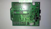
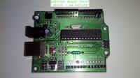
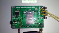
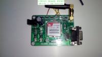
i don't know the name of the company of my boards so i am attaching pictures of the same


my mail address is
vvyasmum92@gmail.com
detailed picture of the boards are here…
https://skydrive.live.com/redir?res...1&authkey=!AM107_XxMCGGX6o&ithint=folder,.jpg
https://sdrv.ms/19J5K3w
please help….
thanks…
i am building a project to control relays with gsm/gprs sim900 module and arduino uno board for my finals, and i am not getting it right.
please help me, and also the connection from sim900 to arduino. i have connected tx of sim900 to rx of arduino and rx of sim900 to tx of arduino, 5v from sim900 to arduino and ground to ground. do i need any other chip in between the connection ?. i also got a code from https://www.edaboard.com/threads/284929/
the code i tried is ...
SoftwareSerial cell(2,3); //Create a 'fake' serial port. Pin 2 is the Rx pin, pin 3 is the Tx pin.
int led1 = 9;
int led2 = 10;
int led3 = 11;
int led4 = 12;
void setup()
{
// prepare the digital output pins
pinMode(led1, OUTPUT);
pinMode(led2, OUTPUT);
pinMode(led3, OUTPUT);
pinMode(led4, OUTPUT);
digitalWrite(led1, LOW);
digitalWrite(led2, LOW);
digitalWrite(led3, LOW);
digitalWrite(led4, LOW);
//Initialize GSM module serial port for communication.
cell.begin(9600);
delay(30000); // give time for GSM module to register on network etc.
cell.println("AT+CMGF=1"); // set SMS mode to text
delay(200);
cell.println("AT+CNMI=3,3,0,0"); // set module to send SMS data to serial out upon receipt
delay(200);
}
void loop()
{
//If a character comes in from the cellular module...
if(cell.available() >0)
{
inchar=cell.read();
if (inchar=='#')
{
delay(10);
inchar=cell.read();
if (inchar=='a')
{
delay(10);
inchar=cell.read();
if (inchar=='0')
{
digitalWrite(led1, LOW);
}
else if (inchar=='1')
{
digitalWrite(led1, HIGH);
}
delay(10);
inchar=cell.read();
if (inchar=='b')
{
inchar=cell.read();
if (inchar=='0')
{
digitalWrite(led2, LOW);
}
else if (inchar=='1')
{
digitalWrite(led2, HIGH);
}
delay(10);
inchar=cell.read();
if (inchar=='c')
{
inchar=cell.read();
if (inchar=='0')
{
digitalWrite(led3, LOW);
}
else if (inchar=='1')
{
digitalWrite(led3, HIGH);
}
delay(10);
inchar=cell.read();
if (inchar=='d')
{
delay(10);
inchar=cell.read();
if (inchar=='0')
{
digitalWrite(led4, LOW);
}
else if (inchar=='1')
{
digitalWrite(led4, HIGH);
}
delay(10);
}
}
cell.println("AT+CMGD=1,4"); // delete all SMS
}
}
}
}
}
i have connected 4 leds at digital pinout of ardiuno uno at pin 9,10,11,12 and same connection goes to the relay through a transistor.
is this code correct? and if yes then i am not getting any results….
i have to submit my project before jan 10 2014…. please help me.
i don't know the name of the company of my boards so i am attaching pictures of the same


my mail address is
vvyasmum92@gmail.com
detailed picture of the boards are here…
https://skydrive.live.com/redir?res...1&authkey=!AM107_XxMCGGX6o&ithint=folder,.jpg
https://sdrv.ms/19J5K3w
please help….
thanks…