Continue to Site

Welcome to EDAboard.com

Welcome to our site! EDAboard.com is an international Electronics Discussion Forum focused on EDA software, circuits, schematics, books, theory, papers, asic, pld, 8051, DSP, Network, RF, Analog Design, PCB, Service Manuals... and a whole lot more! To participate you need to register. Registration is free. Click here to register now.

[SOLVED] Need help using LM358N as instrumentation amp

Status
Not open for further replies.

cmotif

Newbie level 4
Newbie level 4
Joined
Feb 4, 2010
Messages
7
Helped
0
Reputation
0
Reaction score
0
Trophy points
1,281
Activity points
1,348
I am trying to hook up a pressure sensor Pressuresensor.jpg to a National Instruments DAQ analog input to read the pressure reading.

However as the sensor is unamplified it is too noisy to read. I built an instrumentation amplifier to amplify the circuit with some LM358N that I had lying around. I followed the example circuit in the data sheet.
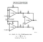
LM358N.jpg

Using an excitation voltage of 12V for the pressure sensor, and the same 12V for the LM358N single supply.
It seems to be working, with a caveat, I do not get the calculated amplification. I am using R1 =100K and R2 = 10K, which should give me a gain of 21.

However using a 500mV square wave, i could only obtain a 1V square wave on the output.

I am not sure what is going on here though I my guess is that the opamp output does not have enough voltage to swing about.

Could some one help me out here?


Thanks!
 
Last edited:

I am not sure what is going on here though I my guess is that the opamp output does not have enough voltage to swing about.
Could some one help me out here?
Thanks!

You must use split supply, unless you provide a specific biasing circuitry for single supply operation.
 
  • Like
Reactions: cmotif

    cmotif

    Points: 2
    Helpful Answer Positive Rating
You must use split supply, unless you provide a specific biasing circuitry for single supply operation.

hi do you mean the non inverting output of the final opamp should be tied to 6 volt via the 100k resistor? which is half of the supply.

otherwise I do not quite understand what you mean by a specific biasing circuit.

- - - Updated - - -

Perhaps , it is better to use INA series Instrumentation amplifiers.

hi, thanks for the recommendation. I am trying to use the opamps I have off hand hence am not purchasing new ones.
 

hi do you mean the non inverting output of the final opamp should be tied to 6 volt via the 100k resistor? which is half of the supply.
The output will look after itself. It is the inputs that should be biased to about half the supply voltage. When the inputs are connected to pins 2 and 4 of the sensor, the sensor should provide this bias.

The circuit looks like it should work fine. Maybe there was just some problem with the way you tested with the square waves. Have you tried it with the sensor?
 
  • Like
Reactions: cmotif

    cmotif

    Points: 2
    Helpful Answer Positive Rating
The output will look after itself. It is the inputs that should be biased to about half the supply voltage. When the inputs are connected to pins 2 and 4 of the sensor, the sensor should provide this bias.

The circuit looks like it should work fine. Maybe there was just some problem with the way you tested with the square waves. Have you tried it with the sensor?

I have tested it out with the sensor with a split supply for the amp and the gain is correct. Hence the problem is how I hooked up the amp.

I am now trying to see if it works just as well with a virtual ground at 6Vdc.
 

Status
Not open for further replies.

Part and Inventory Search

Welcome to EDABoard.com

Sponsor

Back
Top