Need help to convert an industrial servo (1/2 HP . 220) into a DC
- Thread starter jovimon
- Start date
- Status
- Not open for further replies.
schmitt trigger
Advanced Member level 5

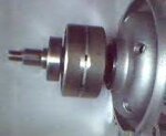
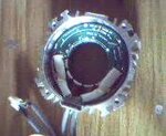
You are only showing the stator...what does the rotor look like? Is it permanently magnetized? Does it have slots?
Other question...is it only two wires coming out from the stator? Does the green circular board contain any type of electronic components?
Other question...is it only two wires coming out from the stator? Does the green circular board contain any type of electronic components?
jovimon
Newbie level 6

You are only showing the stator...what does the rotor look like? Is it permanently magnetized? Does it have slots?
Other question...is it only two wires coming out from the stator? Does the green circular board contain any type of electronic components?
Thank you ST for answer: Here I´m including a pic of the rotor, which is made of permanent magnets (Neodymium I guess). As you can see it has 8 little slots in the middle.
Just two main cables (one with 4 leads, the other with 5 leads), come out from the stator. The green circular board is not easy to remove, but from what I can see, it has three (3) transistors under, and hid between coils.

schmitt trigger
Advanced Member level 5

The "transistors" most likely are hall sensors.
This motor is most likely a three-phase brushless motor.
Do the following:
1- Reassemble the motor
2- Have someone help you rotate the shaft while you take voltage measurements between the leads. Concentrate ONLY on the thicker wires, which must be the ones feeding the coils. The thinner ones must be the hall sensors.
3- Find the wires which produce a voltage between them as the shaft is rotated. NOTE: all of the BLDCs I've ever seen are 3 phase delta connected, so only 3 wires should produce voltage...but they could be wye connected and thus there will be 4 power wires.
4- Feed the those voltage producing wires to a three phase rectifier, and you'll have your DC output.
Electro nS
Full Member level 6
you cannot do that , you donot have a cummutator , and how would you install teh brushes !!!
schmitt trigger
Advanced Member level 5
If the motor is a BLDC, which I think it is, it doesn't need a conmutator. The field is permanent, created by the magnet in the rotor.
The output voltage will be induced on the stator windings.
This is not speculation or opinion. I have right now, as I type this, a BLDC motor in front of me. If I turn the shaft I see the AC voltage on the scope.
The output voltage will be induced on the stator windings.
This is not speculation or opinion. I have right now, as I type this, a BLDC motor in front of me. If I turn the shaft I see the AC voltage on the scope.
jovimon
Newbie level 6
The "transistors" most likely are hall sensors.
This motor is most likely a three-phase brushless motor.
Do the following:
1- Reassemble the motor
2- Have someone help you rotate the shaft while you take voltage measurements between the leads. Concentrate ONLY on the thicker wires, which must be the ones feeding the coils. The thinner ones must be the hall sensors.
3- Find the wires which produce a voltage between them as the shaft is rotated. NOTE: all of the BLDCs I've ever seen are 3 phase delta connected, so only 3 wires should produce voltage...but they could be wye connected and thus there will be 4 power wires.
4- Feed the those voltage producing wires to a three phase rectifier, and you'll have your DC output.
I Find AC voltage between all possible combination of wires (Black, Green, Brown, Yellow/Green). I notice that all combinations with wire Y/G are sensibly of lower voltage than the rest; in fact part of this wire comes out and is screwed to the motor housing (so it must be one ground … I guess). I don´t know what to do at this point.
I´m stepping forward to look for a three phase rectifier and I see a lot of different kinds, so I´d like a recommendation please.
schmitt trigger
Advanced Member level 5
Its a wye connection.
Use a diode on each output then.
Use a diode on each output then.
jovimon
Newbie level 6
Its a wye connection.
Use a diode on each output then.
Sorry for this stupid question (as I told you I just have some basics in electronics). I have four leads coming out of the motor, and all rectifier circuits just three coming in, so which wires to choose (between Black, Green, Brown Yellow/green)?. I have in mind the next circuit.
http://hackedgadgets.com/wp-content/uploads/2010/10/3-phase-bridge-rectifier.png
One last question: As a servo it can reach 5500 rpm, Is at this speed (working as DC) when it can reach the maximum output power?
Thanks ST
schmitt trigger
Advanced Member level 5
That rectfier circuit is fine, just leave the yellow/green open.
Yes, at maximum RPM there will be maximum voltage.
Yes, at maximum RPM there will be maximum voltage.
jovimon
Newbie level 6
that rectfier circuit is fine, just leave the yellow/green open.
Yes, at maximum rpm there will be maximum voltage.
hey! Thankyou very very much s.t.
jovimon
Newbie level 6
That rectfier circuit is fine, just leave the yellow/green open.
Yes, at maximum RPM there will be maximum voltage.
Hi S.T.: I´m back again with a couple of questions, since I don´t want to wrong choosing the most adequate rectifier for this application. ¿Is 380 Watts the maximum output power that I can expect from the converted DC motor?. ¿the chosen rectifier must fit to this range (380 W) + a safety factor (may be 1.5, that is 570 Watt)?
Thanks
schmitt trigger
Advanced Member level 5
Rectifiers are not selected by power, but by maximum reverse voltage and maximum forward current.
Choose a 600V, 3 Amp device.
Choose a 600V, 3 Amp device.
jovimon
Newbie level 6
HI S.T.: Back again. I´m considering using AC current too, for some uses, out of this generator at 220V and 110V; for the first case (220V), ¿ Is just a matter of picking two of the three leads, and for 110V, using a transformer to take it from 220V to 110V? If so, What would be the range (in amps) for the transformer?
schmitt trigger
Advanced Member level 5
I'm afraid that won't be practical. Output voltage and frequency will change with with rotor speed.
- Status
- Not open for further replies.
Similar threads
-
-
How can I implement a BLDC motor to replace a 1 HP motor currently running a pump?
- Started by thannara123
- Replies: 3
-
Not able Convert -22V to adjustable -3V to -16V 10A using lm337 and tip2955
- Started by khuram9172
- Replies: 16
-
i want 24v DC ,40 AMP and 12v DC AMP in 1 SMPS and give the perfect circuit diagram and schematic of it
- Started by vaishnavi pande
- Replies: 1
-


![Converted_file_7077646e[1].JPG](/data/attachments/35/35528-e4056df1fcb6da137e2d374f8599c90c.jpg)