Continue to Site

Welcome to EDAboard.com

Welcome to our site! EDAboard.com is an international Electronics Discussion Forum focused on EDA software, circuits, schematics, books, theory, papers, asic, pld, 8051, DSP, Network, RF, Analog Design, PCB, Service Manuals... and a whole lot more! To participate you need to register. Registration is free. Click here to register now.

Need help regarding generating 60hz frequency using 50hz mains

Status
Not open for further replies.
The 8051 family doesnt have div instruction so i have posted the highly optimized working code.

If you want to change the frequency, edit and compile the sine table.c file using dev c++
and copy paste the new sine table in the pwm code. I have used SDCC for compilation

Untitled.png
 

Attachments

  • pwm.zip
    327.1 KB · Views: 102

Hi Venkatesh!
I am modifying the sine table and declaring fixed values instead of asking ucontroller to calculate, since it gives an error while I compile as it is.(Data segment too large)
Do I need to negate each value with 65535 or shall I avoid 65535 and convert it into hex code? Please clarify.
My MOSFETs are not heating now. I had changed the input gate resistors and replaced with lower values. Now I changed them back to 33 ohms. They are working fine.
 

Hi!
Right now I am using Keil compiler. I will try the above code and show the result.
 

Hi!
The expected PWMs from microcontroller appear square waves one after the other but not at the same time. Due to this, the output appears in intervals distorted as shown in the image.
Please check whether the code is right. I have posted the images, last being the output.

Code:
#include <REG52.H>
#include <math.h>    
 
void pwm_setup(unsigned char);
void io_init();
 
sbit PWMPIN1=P2^0;
sbit PWMPIN2=P2^1;
 
#define HALF_SINE_TABLE_SIZE 128
#define MAX_SINE_VALUE         0xFF
#define TIMER_CLK_FREQ       1000000
 
unsigned int  Timer_period;
 
unsigned short sine_table[];
    int i,j,b;
    unsigned int table = 64;
    unsigned int clk   = 1000000;
    unsigned int freq  = 60;
    //unsigned int ISR_freq = freq * table * 2;
    unsigned int ISR_freq = 7680;
    //unsigned int timer_period = clk / ISR_freq;
    unsigned int timer_per = 130;
    unsigned int a = 0;
    
 
void main()
{
    io_init();
    pwm_setup(60);
      
      for(i= 0; i < (table / 8); i++)
    {
    for(j = 0; j < 8; j++)
        {
    sine_table[b]=65535 - (unsigned int)(timer_per * sin(3.14 * a++/ table) ) ;
            b++;
        }
    b++;
    }

    
    a = 0;
    for(i= 0; i < table / 8; i++)
    {
    for(j= 0; j<8; j++)
    {
    sine_table[b]=65535 - (unsigned int)(timer_per - (timer_per * sin(3.14 * a++/ table) ) ) ;
    b++;
    }
  b++;    
    }
    
    while(1)
        {
            

        }
}
         
void io_init(){
    PWMPIN1 = 0;
    PWMPIN2 = 0;
}         
 
void load_timer(unsigned int Time) {
TH0     = (Time & 0xFF00) >> 8;
TL0     = (Time & 0xFF);
}    
         
void pwm_setup(unsigned char freq){
 
    unsigned int ISR_freq1;
 
    ISR_freq1     = 2 * HALF_SINE_TABLE_SIZE * freq;
 
    //Timer_period = TIMER_CLK_FREQ / ISR_freq;*/
 
    load_timer(timer_per);
 
    TMOD    = 0;
    EA      = 1;
    ET0     = 1;
    TR0     = 1;
}


void timer0() interrupt 1 {
    static int sample = 0;
    static char sign_flag = 0, PWM_out_high = 0 ;
    unsigned int Time_to_load;
    TF0 = 0;
 
    if( ++sample >= HALF_SINE_TABLE_SIZE ) {
        sample = 0;
        sign_flag = !sign_flag;
    }
 
    if(PWM_out_high)
    Time_to_load = timer_per - ( sine_table[sample] * timer_per / MAX_SINE_VALUE );
    else
    Time_to_load = ( sine_table[sample] * timer_per / MAX_SINE_VALUE );
    
    load_timer(Time_to_load);        
    
    if(sign_flag)
    {
        PWMPIN2 = 0;
    
        if(PWM_out_high)
            PWMPIN1 = 1;
        else
            PWMPIN1 = 0;
    }
    else
    {
        PWMPIN1 = 0;
        
        if(PWM_out_high)
            PWMPIN2 = 1;
        else
            PWMPIN2 = 0;
    }
 
    PWM_out_high = !PWM_out_high;
}
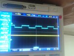
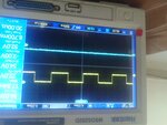

20141003_120103.jpg

20141003_120109.jpg

20141003_120439.jpg

I know working with 8051 code that too for inverter circuit is quite easy. But its taking lot of time.
Please help.
 
Last edited:

khaja_minhaj working with anything is easy. if you have the basic knowledge about it. Do you know how a H bridge works ? If you know then you wont ask the above questions.

First understand what you need to generate with 8051.
 

Yes I understood how the h bridge works. It should work like this.

High side left Mosfet Low side left mosfet high side right mosfet low side right mosfet
1 0 0 1 positive half cycle
0 1 1 0 negative hal cycle
1 0 1 0 zero
0 1 0 1 zero

I think I need to generate pwm signal from microcontroller and that is pulses with varying duty cycle. This varying duty cycle drives the mosfets in h bridge. Am I right? Is there anything I am missing? I still need guidance.
 

you needed to study about sine pwn and how a bridge can work with it.

know about what if your sequence go wrong, what are the waveforms the bridge have, and what is a filter, how to use it.
 

Hi venkatesh!
Sorry for the long gap.
I am still working on it.
The code looks fine since I am getting correct waveforms .I think I need a proper filter to cut out the sine wave from the output. Can you show me one? I have tried the the following one but couldn't get it.
Here are 2 pwms:
**broken link removed**

Here is the output without filtering:
**broken link removed**

I used a kinda filter to which output appeared like this:
**broken link removed**

Here is the output with one input below:
rlc ckt.jpg
 

Hi venkatesh!

Here are 2 pwms:

2 pwm inputs.jpg
Here is the output without filtering:
Output Before filter.jpg

I used a kinda filter to which output appeared like this:
output after filter.jpg

Here is the filter circuit I used:
 
Last edited:

Its only random values. Could not get calculated ones The frequency of pwm is 60hz according to the code.

the frequency is f = 1 / (2pi RC) Is it right way to calculate?
 

Hi,

Its only random values. Could not get calculated ones The frequency of pwm is 60hz according to the code.

the frequency is f = 1 / (2pi RC) Is it right way to calculate?

* Where is the problem in calculating table for sine duty cycle values?
* Your fundamental frequency is about 1.2Hz, this is far away from your desired 60Hz.
* PWM frequency and fundamental frequency only depend on your firmware, not of any R or C.

I guess you are missing some basics.

Klaus
 

i would buy a 12V to 115V 60 Hz ac inverter from a USA company. then i would buy a battery charger to turn 230V 50H to 12 V DC.
 

Hi Klaus!

The code I posted above has sine table values.
But I don't know why the frequency comes is ~1hz. The dc bus voltage I am using is 24vdc instead of 230v dc, so that once I succeed , I would test it with 230vdc. I hope this wont be a problem.

here is the final output, but is still a square wave:

20141021_144159.jpg
 
Last edited:

Correct the code in #26 using #22, you should not use multiplication and division inside the ISR.

Because multiplication and division instructions are not available in your microcontroller.
 

Status
Not open for further replies.

Part and Inventory Search

Welcome to EDABoard.com

Sponsor

Back
Top