Continue to Site

Welcome to EDAboard.com

Welcome to our site! EDAboard.com is an international Electronics Discussion Forum focused on EDA software, circuits, schematics, books, theory, papers, asic, pld, 8051, DSP, Network, RF, Analog Design, PCB, Service Manuals... and a whole lot more! To participate you need to register. Registration is free. Click here to register now.

[SOLVED] need help in figuring our the LED frequency

Status
Not open for further replies.

kdg007

Full Member level 3
Full Member level 3
Joined
Jan 6, 2012
Messages
162
Helped
1
Reputation
2
Reaction score
1
Trophy points
1,298
Activity points
2,420
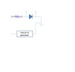
so, i simply connected a LED (forward voltage of 3.3v) with a series resistor (85 ohm), that should give 20mA of current to the LED.
-
then , connected the frequency generator to the series circuit, the LED worked pretty good at about 900kHz .. but when i kept to 10Mhz or more than 3-4 Mhz... the lED just stop working.... why is that ?
-
how to determine the maximum frequency of the LED?
-
i know LED cannot work for higher frequencies but what is the possible explanation for that ? is that the depletion region ? or any losses effect?
 

Firstly, make sure you are not applying AC across the LED from your frequency generator. They only light up when one polarity is applied and LEDs don't like reverse voltages across them.

Assuming the voltage from the generator is constant, there are several factors that would make it dim, there will be some turn-on/turn off delays but the most prevalent effect will be capacitive. The LEDs have fairly large junctions in them and they have a relatively large capacitance, what you have created is an RC filter with R being the series resistor and C the LED itself.

Brian.
 
  • Like
Reactions: kdg007

    kdg007

    Points: 2
    Helpful Answer Positive Rating
can i get a circuit diagram where i can test an LED ? please... i need to figure out this..

- - - Updated - - -

i got the voltage waveform across the LED... the DC offset is 5V from the frequency generator.. is this the right way to test a single LED ?
led.jpg
 

Adding the offset is certainly a good idea becasue you shouldn't apply reverse polarity to an LED and most signal generators produce AC in which half of each cycle could cause damage.

May I ask what your application is? Most LEDs are designed to work on a steady DC supply and those that have to pulse at high frequency require special driver circuits to ensure rapid rise and fall of the voltage. A resistor alone cannot do this, you would need an active current source and sink circuit.

If you are simply testing an LED or tryting to work out it's characteristics, a different method is used and the frequency generator is not needed.

Brian.
 
  • Like
Reactions: kdg007

    kdg007

    Points: 2
    Helpful Answer Positive Rating
i am simply testing an LED to see what is the maximum frequency it could work with .. at 3MHZ.... the waveform looks like noise ....or similar to triangular wave... why does it happen ?
-
A resistor alone cannot do this, you would need an active current source and sink circuit --> what is the right procedure ? can i get a circuit diagram ?i want to try it out..

- - - Updated - - -

The LEDs have fairly large junctions in them and they have a relatively large capacitance ---> what is the effect of junction capacitance for higher frequencies ?
 

All diodes have capacitance

.... which often used when reverse biased, in which case the leakage is low and C vs V drops for increasing voltage until leakage begins to rise just before maximum rating.. (-5V for all LEDs )

- bigger diodes have more capacitance.

- 5mm LEDs are around 500pF at 0V hence the triangular waveform

But for emission to occur the current must flow thru the doped junction rather than capacitive path,
so LED dims out at RC LPF break point.

The ESR of the 5mm LED is around 10~15 ohms which can be added to your external R.

If you wanted to optimize speed with lowest ESR for RC time constant,

Drive it with an emitter follower biased to a value greater than LED rating of 20mA and properly biased to swing 0.5V~1V around the Vf threshold of ~2.8V for white and ~1.4V for Red.

Then you might get 10MHz.

3W LED's have an ESR in the 10 mOhm area. some<1.
 
With correctly adjusted offset, you should be able to drive a LED with a function generator.

Besides a cut-off frequency set by the series resistor and LED capacitance, there's also a frequency limit in the optical transmission. Unfortunately, the bandwidth of visible LEDs is mostly unspecified. As far as I remeber, it varies considerably with LED technology.

For specified dynamic behaviour, refer top IR LEDs.
 
  • Like
Reactions: kdg007

    kdg007

    Points: 2
    Helpful Answer Positive Rating
Emitter Follower will give an output impedance much lower than the ESR of the LED to give optimal response.

0ce70e04ff3136f72ea8f7b3ab35ec8f.png


If Rs =50 Ω driving base with Beta=100, Re=0.5 Ω to Anode and Cathode to ground. Caution to not overdrive LED with proper offset to Vf and swing of 0.5V (e.g. Red Led Voffset=1.25V with swing from 1.2 to 1.7 will give a faster square wave response to at least 10MHz. Adjust offset by 0.1 increments to match diode.
Add current limiting resistor in collector to protect LED.

All the voltage swing in the LED due to the internal ESR , whereas the Vf threshold is typically measured at the 10% of rated current or 2mA in this case.

It is possible to get at least 2 orders of magnitude of light out and the LED and maybe 3, but reception is limited range.

For optical communication a narrow bandwidth such as 16QAM or 64QAM is better for the receiver such as used by ADSL modems and dialup modems.

It is better to have the directivity of a laser diode or the higher current capability found in IR diodes.

Daylight blocking filters reject ambient light so IR is preferred.

If you like to experiment, make a fibre optic link using mono-filiment heavy fishing line and drill hole between two LEDs with 1/32 drill and use clear epoxy . Connect a TI transimpedance amp with emitter follower and a switch for both ends. YOu can use the LED as a Photo Diode but performance is much less than typical 0.5mA/mW of a good PD. Now you can create a half duplex fibre optic link.
 
Last edited:
  • Like
Reactions: kdg007

    kdg007

    Points: 2
    Helpful Answer Positive Rating
All diodes have capacitance

.... which often used when reverse biased, in which case the leakage is low and C vs V drops for increasing voltage until leakage begins to rise just before maximum rating.. (-5V for all LEDs )

- bigger diodes have more capacitance.

- 5mm LEDs are around 500pF at 0V hence the triangular waveform

But for emission to occur the current must flow thru the doped junction rather than capacitive path,
so LED dims out at RC LPF break point.

The ESR of the 5mm LED is around 10~15 ohms which can be added to your external R.

If you wanted to optimize speed with lowest ESR for RC time constant,

Drive it with an emitter follower biased to a value greater than LED rating of 20mA and properly biased to swing 0.5V~1V around the Vf threshold of ~2.8V for white and ~1.4V for Red.

Then you might get 10MHz.

3W LED's have an ESR in the 10 mOhm area. some<1.
-
so, the bigger the capacitance, the lower frequency the LED will work ?
 

Please tell us what you mean by "LED will work".

LEDs are used for two purposes, providing illumination, either as area lighting or to indicate the state of equipment operation, or, as a source of light for data signalling.

You seem to be wanting to know what frequency an indicator LED will work at. They are not designed to work at a 'frequency' at all, they normally work on DC. Granted, they will flicker when the current through them is varied but that isn't what they are designed to do. I can't understand why you are concerned over using a device in a way the manufacturer never intended.

Also explain what you are using to view the waveform. An LED converts current into light so if you want to check it's response time you need to measure the light output. It sounds like you are using an oscilloscope across the LED itself which is not a valid measurment and simply demonstrates a capacitance beng charged and discharged.

Brian.
 
  • Like
Reactions: kdg007 and FvM

    FvM

    Points: 2
    Helpful Answer Positive Rating

    kdg007

    Points: 2
    Helpful Answer Positive Rating
I agree these LEDS are not intended to be used for high speed communication. IR with IRDA (100Kbps) IRDA2 (4Mbps) transceivers or for long haul Laser diodes work better.

I have not tested them but the bigger LEDs also have much lower ESR, so no idea what effective bandwidth is, probably lower,

but my point was that the generator 50ohm was also limiting the bandwidth of current being much bigger than the component's ESR and the junction capacitance was draining most of the current a the limit. But I'm not really sure of the physics at that speed.
 
Last edited:
  • Like
Reactions: kdg007

    kdg007

    Points: 2
    Helpful Answer Positive Rating
so, i simply connected a LED (forward voltage of 3.3v) with a series resistor (85 ohm), that should give 20mA of current to the LED.
-
then , connected the frequency generator to the series circuit, the LED worked pretty good at about 900kHz .. but when i kept to 10Mhz or more than 3-4 Mhz... the lED just stop working.... why is that ?
-
how to determine the maximum frequency of the LED?
-
i know LED cannot work for higher frequencies but what is the possible explanation for that ? is that the depletion region ? or any losses effect?

they operate in one cycle and turn off in the other the point is the change in voltage from positive to negative is so fast that our eye fails to recognise it in real time
 
  • Like
Reactions: kdg007

    kdg007

    Points: 2
    Helpful Answer Positive Rating
Status
Not open for further replies.

Part and Inventory Search

Welcome to EDABoard.com

Sponsor

Back
Top