Continue to Site

Welcome to EDAboard.com

Welcome to our site! EDAboard.com is an international Electronics Discussion Forum focused on EDA software, circuits, schematics, books, theory, papers, asic, pld, 8051, DSP, Network, RF, Analog Design, PCB, Service Manuals... and a whole lot more! To participate you need to register. Registration is free. Click here to register now.

Need help identifying SMD capacitor

Status
Not open for further replies.

ando1

Newbie level 4
Newbie level 4
Joined
Dec 15, 2017
Messages
7
Helped
0
Reputation
0
Reaction score
0
Trophy points
1
Activity points
74
Hi,

I am new to the forums as I just found it while researching a fix for my Sonos connect:amp. I found a blown cap on the logic board and need help identifying the value and type so I can order a replacement. Many thanks.

Andy
 

Attachments

  • caps.jpg
    caps.jpg
    546 KB · Views: 285
  • failed_part_2.JPG
    failed_part_2.JPG
    255.6 KB · Views: 246
  • failed_part_1.JPG
    failed_part_1.JPG
    37 KB · Views: 467

Clearly there is no marking on the upper face, which would suggest unsoldering to see if there is something on the other side, but depending on its size (eg footprint 0402), there may not even be any marking. In cases like these, an alternative is to try to identify the surrounding circuit to know what the function of that component is; in many cases (such as Vcc decoupling), the value of the capacitor does not have to be exact.
 

Hi,

it seems the capacitor "connects" GND with the shield of the (ethernet?) connector.

I assume a lower value should do. 1nF? 10nF?

Klaus
 

These parts are not likely to have any markings on any side. From its location, I would say the it is a decoupling cap - probably the same value as the one right beside it. My educated guess is that it is a 0.01 to 0.1µF capacitor. If one side is connected to ground, just solder in a value in this range and hope that this is the only problem.

When a cap blows like that, it means that it was way over the voltage rating for the device.
 

Thanks all for the quick responses!

andre_teprom: I de-slodered the cap and it fell apart on me so I cannot see any marking on it at all.

KlausST: The cap is near the Ethernet ports of the connect:amp so I think you are right about that. One side of the cap ohms directly to GND so you I believe are spot on

SLK001: I was thinking it was the same value as the one beside as well. Since they do not have markings, is there a way I can tell a value from just a DMM? Maybe measuring the resistance? Sorry it has been a while since I did any component level testing an I am a bit rusty.

Does anyone think that it is an 0805 size? I found some on Amazon that I could get in pretty quickly: https://www.amazon.com/gp/product/B0015A6ZVM/ref=ox_sc_act_title_1?smid=AZHZ102UTKBMA&psc=1
 
Last edited:

The footprint seems large enought to fit a number of sizes, but it would be better you measure by yourself. Just out of curiosity: Are you about to replace this part because the board is not working, or to turn back the equipment to its original condition? Due to the region where it was placed on the board, this seems not to be functional component, but just to protect against surges or to filter EMI.
 

The resistors near your caps are 0603s (this is the smallest marked resistor). Comparing the size of your cap with the ICs on the board, your size for the cap is 0805. But grab your calipers and verify the sizes for yourself.
 
  • Like
Reactions: ando1

    ando1

    Points: 2
    Helpful Answer Positive Rating
Thanks Andre. So the long story is I purchased a non-working Sonos Connect:AMP from eBay with the intent to repair it. Since these are $500 new and I am a cheapskate :) (I only paid $100 for it) I thought it would be a way to get one of these for a good price and also gain some experience with repairing it. I am DIY guy and have done component level troubleshooting in the past (a looong time ago) and have experience with DMMs and soldering. Before purchasing, I did some research on common no-power issues with the Connect:AMP and normally the cause is a short in the input power supply. There is an inline fuse and a bias converter that are the likely components that fail, so I gambled and purchsed the AMP. When I started troubleshooting I noticed that the input power supply was not the issue so I had to start digging deeper. The AMP does power on but does not fully boot. My best guess is that the AMP received a surge (possibly plugged into POE or lightning strike) through the Ethernet port and that is causing the failure.
 

Hello ando1,
Can you please refer to your modified picture below:

8tQ4tjH.jpg


You need to do an ohms check between the faulty capacitor marked by the RED
and BLACK arrows.

Check the resistor marked by the PURPLE arrow.

Have a close look at the track marked with the GREEN arrow.

You need to find what components are tied to the vias marked by the PALE BLUE arrows
on the other side of the PCB.
In my opinion it seems a substantial amount of current has been passed through that track I mentioned above.
Regards,
Relayer
 
  • Like
Reactions: ando1

    ando1

    Points: 2
    Helpful Answer Positive Rating
Thanks Relayer. I will check those points and report back soon. I have a weekend full of kids sports and taking them to see the new Star Wars movie. I may be able to get some time tomorrow.

Andy
 

@Relayer

Answers to your earlier post:

- The CAP measures open. I have since removed it and it fell apart so it is def burned up
- The resistor is open so it is dead
- The green arrow shows the residue of the cap and/or resistor that burned up
- I did identify the points you indicated in PALE BLUE and posted some pics below

IMG_0169.JPG

I have ordered the caps and resistors and plan on replacing all the components in that section. I also did some more investigation and found a burned up inductor that was under a metal housing. That circuit appears to be the transceiver circuit for the Ethernet ports as I Googled the chip in the last pic.

IMG_0165.JPGIMG_0163.JPG

That inductor measures open. It appears to be a size 0603 but I am not sure about the value. Any ideas?
 

That inductor measures open. It appears to be a size 0603 but I am not sure about the value. Any ideas?

Look for a circuit for those chips in their datasheet or apnote. Without a schematic, all we can do is guess the inductor value.
 

Look for a circuit for those chips in their datasheet or apnote. Without a schematic, all we can do is guess the inductor value.

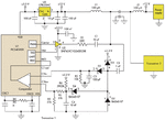
Thanks SLK001: I found this circuit by a Google search. It seems pretty similar to the one that is on my board and the inductors are 100uH, I ordered a kit from eBay that has a range of values form 240NH to 22uH but couldn't find an 0603 inductor over 22uH. I am hoping I can find the value or I will try with some of the lower values first I suppose. I am not sure what the purpose of that inductor is in my circuit but hope that trying a few different values won't hurt it.

Here is the example circuit I found:

Transceiver circuit example.gif
 

Yes, 78Q2123 is an ethernet PHY. But how is the schematic in your latest post related to it? It's a completely different circuit.

An inductor or ferrite bead near an ethernet PHY is typically a power supply filter. Seeing it burned suggests that there are more components damaged.
 

@FvM - The schematic I posted is similar to the one on my board. This board is from a Sonos Connect:AMP that I came into. It wasn't working when I received it and I have found that there are several caps and resistors from what appears to be a Ethernet decoupling circuit that were burned out. The inductor is part of the Fast Ethernet transceiver tat is physically near that decoupling circuit. My goal is to replace the damaged components in the hopes that I can get the amp working again.
 

Status
Not open for further replies.

Similar threads

Part and Inventory Search

Welcome to EDABoard.com

Sponsor

Back
Top