DMC69
Newbie level 3

PIC16f84a
hey guys.. i hope i'm posting in the right section... i got a problem... am trying to make a count-up timer using a 7 segment display with a decoder and PIC... with two push buttons RA0 as reset and RA1 as start... initial display is 00 and when i press start it starts counting up with a delay of .5s from 00-99... what i want is that when it reaches 99 it stays 99 until i press reset... my code only counts up and after it reaches 99 it immediately goes to 00... plase help... i've attached my code in my post and a schematic diagram... am using MPLAB IDE 8.50 and proteus 7.4 and also i'm using assembly
***********************************************
LIST P = 16f84A, F = INHX8M
INCLUDE <P16F84.INC>
__CONFIG _CP_OFF & _WDT_ON & _XT_OSC
digitctr1 equ 0ch
digitctr2 equ 0dh
delayctr equ 0eh
goto initPIC
delay movlw 07h
movwf delayctr
d1 Sleep
decfsz delayctr
goto d1
return
initPIC BSF STATUS, RP0
clrf TRISB
movlw 03h
movwf TRISA
movlw 0ah
movwf OPTION_REG
BCF STATUS, RP0
rst CLRF PORTB
clrf PORTA
startchk BTfss PORTA, 1
GOTO startchk
movlw 09h
movwf digitctr1
rstdgt movlw 09h
movwf digitctr2
inrdigit call delay
incf PORTB
DECFSZ digitctr2
goto inrdigit
call delay
movlw 0ah
addwf PORTB
movlw 0f0h
andwf PORTB
decfsz digitctr1
goto rstdgt
movlw 09h
movwf digitctr2
extra call delay
incf PORTB
DECFSZ digitctr2
goto extra
restart BTFSS PORTA, 0
goto restart
goto rst
END
********************************************
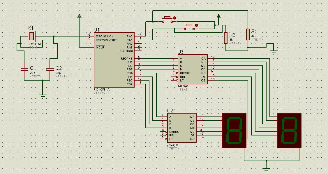
here's the design... my RB0-RB3 is the least significant and RB4-RB7 is the most significant
hey guys.. i hope i'm posting in the right section... i got a problem... am trying to make a count-up timer using a 7 segment display with a decoder and PIC... with two push buttons RA0 as reset and RA1 as start... initial display is 00 and when i press start it starts counting up with a delay of .5s from 00-99... what i want is that when it reaches 99 it stays 99 until i press reset... my code only counts up and after it reaches 99 it immediately goes to 00... plase help... i've attached my code in my post and a schematic diagram... am using MPLAB IDE 8.50 and proteus 7.4 and also i'm using assembly
***********************************************
LIST P = 16f84A, F = INHX8M
INCLUDE <P16F84.INC>
__CONFIG _CP_OFF & _WDT_ON & _XT_OSC
digitctr1 equ 0ch
digitctr2 equ 0dh
delayctr equ 0eh
goto initPIC
delay movlw 07h
movwf delayctr
d1 Sleep
decfsz delayctr
goto d1
return
initPIC BSF STATUS, RP0
clrf TRISB
movlw 03h
movwf TRISA
movlw 0ah
movwf OPTION_REG
BCF STATUS, RP0
rst CLRF PORTB
clrf PORTA
startchk BTfss PORTA, 1
GOTO startchk
movlw 09h
movwf digitctr1
rstdgt movlw 09h
movwf digitctr2
inrdigit call delay
incf PORTB
DECFSZ digitctr2
goto inrdigit
call delay
movlw 0ah
addwf PORTB
movlw 0f0h
andwf PORTB
decfsz digitctr1
goto rstdgt
movlw 09h
movwf digitctr2
extra call delay
incf PORTB
DECFSZ digitctr2
goto extra
restart BTFSS PORTA, 0
goto restart
goto rst
END
********************************************
here's the design... my RB0-RB3 is the least significant and RB4-RB7 is the most significant