Continue to Site

Welcome to EDAboard.com

Welcome to our site! EDAboard.com is an international Electronics Discussion Forum focused on EDA software, circuits, schematics, books, theory, papers, asic, pld, 8051, DSP, Network, RF, Analog Design, PCB, Service Manuals... and a whole lot more! To participate you need to register. Registration is free. Click here to register now.

need help and info on psu components

Status
Not open for further replies.

sherazi

Banned
Full Member level 6
Joined
Feb 15, 2010
Messages
388
Helped
61
Reputation
126
Reaction score
61
Trophy points
1,318
Location
Muscat, Oman, Oman
Activity points
0
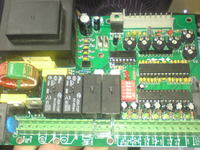
i had a question...in most power supply pcb i found special sort of caps with transformr, (a ring wounded two coils as can be seen in the pics attached... )
,


**broken link removed**
 

Switch mode power supplies are efficient in terms of power conversion but because the 'chop' the power to reduce it rather than convert it to heat as a linear regulator would do, they produce a high level of interference.

The coils on ferrite rings and the capacitors are there to reduce the amount of chopping signal that would otherwise reach the power cord and cause radio interference.

The rings (toroids) have the property of increasing the inductance of the coil around them and at the same time they concentrate the interfering signal inside the ring itself. Some other type of choke would concentrate the signal in the core but radiate it outwards.

The capacitors are also part of the filter but as they are connected across the AC power cord, they have to be safety rated types. Although normal capacitor will do the job equally well, they could be more prone to damage from power surges and it they were to go short circuit they would link the two power wires and possibly cause damage elsewhere. If you look closely, they will have AC voltage ratings on them, normal capacitors normally only have DC ratings.

Brian.
 

    sherazi

    Points: 2
    Helpful Answer Positive Rating
thanx alot it helped alot... but can u suggest me that why this board contains such elements ... as it is not a smps... i have to work on the same sort of circuit...

its control board for gate opner and is using 7805 as regulator. it also provides 12 and 24 volts for peripherals...

i am confused that why should a linear psu contain these elements...

has it to do somthing to povide much stable and ripple free supply.. or what?


i got the reason.. its because the micro should get most stable and noise free supply...

now what values should i use to get the best result does any one have a schematic or so....

Added after 13 minutes:

such sort of schematic.... what values should be used... if there are better circuits plz help in that case tooooo
 

Status
Not open for further replies.

Similar threads

Part and Inventory Search

Welcome to EDABoard.com

Sponsor

Back
Top