Continue to Site

Welcome to EDAboard.com

Welcome to our site! EDAboard.com is an international Electronics Discussion Forum focused on EDA software, circuits, schematics, books, theory, papers, asic, pld, 8051, DSP, Network, RF, Analog Design, PCB, Service Manuals... and a whole lot more! To participate you need to register. Registration is free. Click here to register now.

Need a help about Xenon flash tube

Status
Not open for further replies.

cnandha19

Member level 3
Member level 3
Joined
Aug 28, 2015
Messages
59
Helped
1
Reputation
2
Reaction score
1
Trophy points
8
Activity points
604
SMART STROBE


750w-strobe-board.jpg
Smart S**broken link removed**trobe: 750w AC flash stroboscope

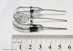
1.Please tell me the working principle of the smart strobe 750W. I am using the (FT-ST-S40w) Spiral Helical strobe flash tube lamp.Per minute how many times it can flash. If i change the 40Watts into 100watts then how many times it can flash per minute.

XENON FLASH TUBE
**broken link removed**
FLSAH TUBE LINK :**broken link removed**

strobe-s1.jpg
 

Rated for 750W xenon
Specs
• Working voltage: 220v AC
• Maximum power: 750w
• Flash rate: variable 1~10 Hz (flashes per second)
• PCB Size: 65x187mm
PLEASE NOTE: This product requires a high amperage socket and circuit breaker of 10A-16A to allow maximum power

Lower power tube you have, may go faster with modification, but not much
 
1. Flash rate: variable 1~10 Hz (flashes per second)

1. Will this SMART STROBE and flash tube flash every 1 sec once.?
2. how to calculate flash rate per second using 1~Hz.
3. Flash per sec depends on flash tube or SMART STROBE?
 
the principle is usually repetitive capacitor discharge/charge...if the cap can get up to the flashover voltage in time, then you can flash at whatever frequency you want as long as flash period is below about 100us becuae the flash lasts about 100us...obviosusly the power ssource has to be able to charge up the cap back up to voltage in time too.
 
1.I am getting flashes 5-6 times per second how to vary the frequency to get flash tube flashes per second ?? pls help me
or any links to study depth
 

The data sheet says 40 watts, and that would be limited by temperature rise of the flash tube.

Discharge energy is in Joules (watt seconds) So you can discharge 40 Joules per second continuously at full rated power.

You could charge up a capacitor bank to 40 Joules and in theory flash once per second.
The flash itself will be very short, but the total energy dissipated is what matters.

If you want to flash 100 times per second, you can, but the capacitor bank should only store enough energy for 0.4 Joules per flash to run the tube at maximum full rated power.

At that high a flash rate (and low energy per flash) you will only see a dull white continuous glow.

It will be much more impressive at slow flash rates with higher peak energy.
 
1.I am getting flashes 5-6 times per second how to vary the frequency to get flash tube flashes per second ??

On the right side of the board you see one pulse transformer that produces the trigger signal for the flash. The middle leg in the flash tube (connected with the external wire electrode) takes the trigger voltage and initiates the flash. Your flash tube is coiled and has considerable inductance. The trigger transformer takes a short pulse of current and produces a high voltage pulse that causes the flash tube to conduct and the discharge the main capacitor almost fully.

To get more flashes per second, you will need to:

1. Reduce the capacitance value of the main capacitors (energy storage capacitors) so that they charge fast (0.1 uF to 0.01uF may be ok) between the flashes.

2. Modify the relaxation oscillator that determines the flash rate (reduce the capacitance and/or resistance) - do not reduce the capacitance too much otherwise the trigger voltage may be too low.

3. To see whether the flash is working, you look at a moving object (say the fan rotating) and you will see discontinuous steps.

4. You can use a potentiometer to adjust the pulse rate (there are already potentiometers fixed: what are they for?)
 
I connected the SMART STROBE and flash tube 40W without giving external trigger though sockets. when i switched "ON" and "OFF" some times it flashes.

How the smart strobe flashes without giving an external trigger?
Is there any vibrator used in the smart strobe?
Which input makes it "ON"?
 

1.I am getting flashes 5-6 times per second how to vary the frequency to get flash tube flashes per second ?? pls help me
or any links to study depth
Clearly there are TWO potentiometers and you report only 1 result.b The web page indicates it is NOT a Cap Discharge device. All gas tubes behave like negative resistance switches with a high trigger voltage but low conduction voltage. The current limit is determined by some a pot controlled active series current limiter. The Rep rate is a pot controlled Relaxation oscillator. The air-core inductor, provides the high voltage trigger, then the rectified? AC line provides the follow-on current.

see web snip below.

A capacitor-LESS design powers the flash tube lamp directly from high power mains voltage, allowing a light weight module, and low-cost, high-power device. It requires NO other external parts (except the lamp of course).


FEATURES:
Variable flash rate knob
Variable flash brightness knob
No-Heat operation board
Synchronization input port (single flash trigger command)
light-weight - no capacitors needed
 
I believe nobody can answer your detail question without knowing circuit details of the stroboscope, or he's just guessing.

Looking at the power supply components, I doubt that the circuit can actually output "750W".

A capacitor-LESS design powers the flash tube lamp directly from high power mains voltage.
How? Xenon tube pulse currents are in a 10 to at least several 100 A range. How to source it from the mains without a storage capacitor?

The current limit is determined by some a pot controlled active series current limiter.
Some advanced flasher circuits are using IGBTs to switch-off the discharge. I don't recognize suitable components on the board photo, except for a TO220 device without any heatsink.
 
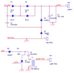
Here i had:grin: attached my circuit below


flasher.png


1. How to change the flash intensity using this circuit.
2. Which components we should change for the different intensity variation.
 
Last edited by a moderator:

You had better hope and pray that flash lamp turns off at the zero crossing.
Because if it doesn't something is definitely going to blow up.
 
1. How to change the flash intensity using this circuit.
2. Which components we should change for the different intensity variation.

C1 determines the flash intensity. The flash goes out when the voltage is drained to about 250V- this is not clear because that depends on the tube design. The capacitor dumps all the energy into the tube till the voltage becomes low enough to turn the tube off.

The design is not good- the tube cannot take high power on a continuous basis. There is no current limiting device.

Only C1 is needed to be increased to increase the intensity.
 
That is not true that the tube goes out below 250v.

It may not turn on below 250v, but once alight, if fed from a current source it will stay conducting down to a surprisingly low voltage.

This circuit is fed directly between mains active and neutral through diodes D1 and D2 without any current limiting.
Its going to draw essentially an unlimited current and either explode the tube or destroy D1 and D2.

Arcs have a negative resistance and grow to infinite size unless the power source is current limited.
I wish you luck, you obviously have not yet built and tested this circuit.

Just be prepared for one hell of a bang when you first trigger that tube.
 

That is not true that the tube goes out below 250v..

The Xe arc lamps that work continuously at 250V (around that) have a different design- the electrodes are pointed W and are very close (about 1 mm or so) - they are run at const current (more or less like the common fluorescent lamp) and very stable arcs can be obtained for long time. Many camera flash tubes are straight with short gaps between the electrodes- but they anyway run on batteries. The helical and U-tube designs of flash lamps usually help them to shut off (the electric field does not follow the curvature well) but both inductance and capacitance are increased.
 

If the electrodes are only 1mm apart, how is that long curly tube supposed to emit light along its entire length ?
I have some of those tubes here and the electrodes are right at the extreme ends of the curly tube.

Yes, long stable very thin arcs of only a few milliamps continuous current are certainly possible when fed from a high voltage constant current source.

Flash lamp supplies fed from charged capacitors obviously extinguish when the capacitor discharges enough, which is usually right down to a very few volts.
Its certainly not because the xenon tube stops conducting below 250v.

Even a straight xenon lamp a foot long will discharge a capacitor bank down to only a few volts.

If you fire a xenon tube from a very high voltage trigger, usually at least 4Kv, the tube conducts and only a fairly low voltage is required to sustain a continuous arc discharge.

If its continuously fed from the mains, as this circuit is, the arc will be continuous.
As there is no current limit, the arc will grow until it fills the tube and bursts the glass envelope.

An arc does not always extinguish at the zero crossings, as ac arc stick welders weld continuously even when the arc polarity goes through zero and reverses.
Xenon tubes will also do that.

These same arc stick welders are fed from a constant current transformer.

Its been a long time, but I used to design very high power pulsed laser power supplies for some defence department projects.
These all used fairly large xenon tubes.
There is something called "the explosion limit" with these tubes, which is the Joule energy you can safely dissipate per pulse.
And they really do explode if you exceed the rating.
 

Short arc tubes are different than long arc tubes. https://en.m.wikipedia.org/wiki/Xenon_arc_lamp.
Short tubes conduct more current and have lower trigger and extinguishing voltages as well as lower ESR.

Neither are intended for flash.

Flash tubes are different in that they cannot dissipate continuously the peak power discharged.

Beware of explosion limits as pointed out before and use safe handling procedures.
 
Last edited:

The classic strobe design was a capacitor discharge arrangement (often with some series L to lengthen the pulse), and you see these in things like timing lights, camera flashes and flashlamp pumped lasers where a short very high intensity discharge is critical.

The entertainment industry realised some years back that very short (tens of microsecond) pulses were actually not important for many of their uses and that actually connecting a strobe tube directly across the mains and firing it at a variable phase angle relative to the zero crossing (To control the intensity) actually works just fine.

Rather hard on the mains waveform possibly, but it works and removes the need for the very bulky photoflash caps, Martin lighting were an early player with the Martin 'Atomic' strobes (Which are beasts).

The PSC at a typical mains socket is of the order of a few thousand amps, probably in the same ballpark as the peak current in a simple minded cap discharge strobe (Especially one lacking a PFN), so this works fine.

Short arc xenon is a totally different thing, running huge lamp pressures (30Atm when hot is typical), short interelectrode distances (a few mm) and (once lit) low voltages (~20V or so normally) at large current (Many tens of amps), these are basically a replacement for carbon arc lamps in applications like movie theatres, and have nothing in common with strobes.

a 40W/s tube can handle 40J per pulse @ 1Hz, 4J/pulse @ 10Hz, it is actually a very small tube by todays standards, and may be too small for that circuit to drive with reasonable tube life.

Regards, Dan.
 

Thanks for disclosing the operation principle of the "capacitor-less" xenon flasher circuit. That's a real brute force method to operate a flash tube.

I agree with the comments that a short xenon tube won't necessarily survive this supply method. I presume the circuit is designed for 127 VAC only.

Obviously the only way to vary the intensity is to adjust the trigger phase angle. C1 is only providing the energy to ignite an arc that burns with the half-wave rectified mains voltage.

Another point to consider is that the circuit is violating any existing power quality standards, it's operation might cause severe mains interferences. At least in the EU region it's not tradeable, and I believe neither in the US.
 

Status
Not open for further replies.

Part and Inventory Search

Welcome to EDABoard.com

Sponsor

Back
Top