Continue to Site

Welcome to EDAboard.com

Welcome to our site! EDAboard.com is an international Electronics Discussion Forum focused on EDA software, circuits, schematics, books, theory, papers, asic, pld, 8051, DSP, Network, RF, Analog Design, PCB, Service Manuals... and a whole lot more! To participate you need to register. Registration is free. Click here to register now.

need 12 v dc to 240v ac 500w inverter circuit

Status
Not open for further replies.

Harish Achar

Member level 1
Member level 1
Joined
Mar 15, 2012
Messages
39
Helped
3
Reputation
6
Reaction score
3
Trophy points
1,288
Activity points
1,575
i want to make an inverter ckt of i/p vg 12v dc and o/p vg 240v ac , i need 2 - 3A current at o/p side.
and i wants to do it without center tap transformer and i can use 12v to 240v stepup transformer.
 

Have you decided which controller you'll use? SG3524, SG3525, microcontroller or something else?

If you want to do it without center tap transformer, use full-bridge topology instead of push-pull.

If the transformer primary voltage rating is 12V, secondary rating of 240V won't be enough.

Hope this helps.
Tahmid.
 

i want to make an inverter ckt of i/p vg 12v dc and o/p vg 240v ac , i need 2 - 3A current at o/p side.
and i wants to do it without center tap transformer and i can use 12v to 240v stepup transformer.

Do you want to be cheap ?
Do you need square, pure sine, modified sine wave on output ?

What design SMPS or iron core ?


You can first search EDABoard you can find lots of inverters projects.
 

thank u for reply,

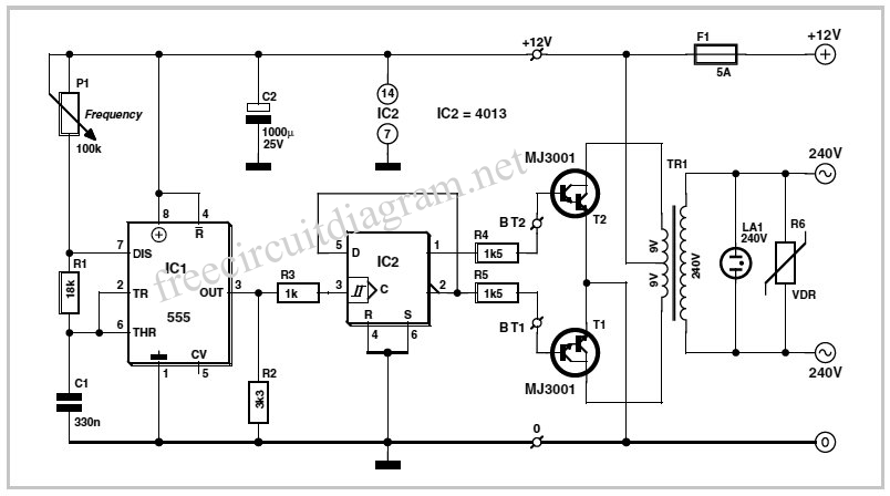
I dont use any microcontroller, using a 555 ic convert 12v dc to 12vdc 50hz square wave and fetch it to 4013(d - f/f) ic to get 2 toggle signal of 12v 50Hz and then fetch these 2 signal to MJ11032 to amplify current which is connected to center tap transformer (12 to 240v step up) but am unable to get 25A(getting 12A)current at primary side pls help me..i need at least 2A at secondary.
 

What transformer you have. Trafo core is enough big?

You should use several transistors in parallel to get higher current.


Post circuit.

- - - Updated - - -

Circuit is this :

12V-Inverter-Schematic.gif


https://farrukh-2dayselectronics.blogspot.com/2010/08/12v-inverter-circuit-using-4013.html
 

thank u for reply,

I dont use any microcontroller, using a 555 ic convert 12v dc to 12vdc 50hz square wave and fetch it to 4013(d - f/f) ic to get 2 toggle signal of 12v 50Hz and then fetch these 2 signal to MJ11032 to amplify current which is connected to center tap transformer (12 to 240v step up) but am unable to get 25A(getting 12A)current at primary side pls help me..i need at least 2A at secondary.

This won't be a very good circuit, especially for 500W.

Use a PWM controller such as SG3524 or SG3525.
For driving the transformer, use MOSFETs to minimize losses and maximize efficiency.
Use feedback to maintain/regulate output voltage.
 

thank u for reply,

I dont use any microcontroller, using a 555 ic convert 12v dc to 12vdc 50hz square wave and fetch it to 4013(d - f/f) ic to get 2 toggle signal of 12v 50Hz and then fetch these 2 signal to MJ11032 to amplify current which is connected to center tap transformer (12 to 240v step up) but am unable to get 25A(getting 12A)current at primary side pls help me..i need at least 2A at secondary.

Also, on secundar if you have lets say 2A, that is around 450W, on other side, on battery side, you need to give 37,5A at least!!! (theoretically in real life more). With 25A on battery side its 300W, on 220V side you can get 1,36A.

You should have good battery.
 

At full power at lowest battery voltage (let's take that as 10.5V under full load), the current from the battery (assuming 80% efficiency of the inverter) is [(500/10.5)/0.8] = 59.5A.

Now, try to imagine the losses you will have when using power transistors. That's why it's suggested to use MOSFETs instead.
 
This won't be a very good circuit, especially for 500W.

Use a PWM controller such as SG3524 or SG3525.
For driving the transformer, use MOSFETs to minimize losses and maximize efficiency.
Use feedback to maintain/regulate output voltage.

thanks Tahmid,

Do u have any circuits or link (it must be a cheaper ckt).
 

is it necessary? can u explain what is the problem if i use single mosfet( data sheet shows it will give max 55A current)..............
 

Also manufacturer datasheet tell on what temperature, usually they give data for 25C. Its hard to keep 25C of parts, where even ambient temp is over that. ;-) Marketing is amazing.

But best learning is if you try to make, theory is nothing without practical exams. When device get hot you can fast turn off, measure and monitor, and make conclusions.

thank you for ur suggetions:)
 

In post 8, I've shown that maximum current (average) will be 59.5A. Peak current is push-pull converter can be 1.4 times average current, which in this case will be 1.4 * 59.5A = 83.3A. You just crossed the current limit (by A LOT) before we even got to the power loss calculations!
 

Thank u

How many MOSFETs I have to use for better performence(500watt).....
 

Depends on the efficiency you want. Let's say you'll use IRF3205. Let's take RDS(on) to be a constant 8mΩ. Highest average current was calculated to be 59.5A. P = (I * I * R).

For simplicity, let's just consider the conduction losses.
If you use 5 IRF3205's in parallel in one leg, the RDS(on) is 1.6mΩ. Maximum power dissipation in the 5 IRF3205's is (59.5 * 59.5 * 0.0016)W = 5.6644W. If you use 4 IRF3205's instead of 5, power dissipation is 7.0805W. If you use 3 IRF3205's instead, power dissipation is 9.441W.

Decide which is okay for you. Then select accordingly. The lower the power dissipation, the lower the losses, the lower the heat, the higher the efficiency.

Hope this helps.
Tahmid.
 

  • Like
Reactions: FvM

    FvM

    Points: 2
    Helpful Answer Positive Rating
Status
Not open for further replies.

Part and Inventory Search

Welcome to EDABoard.com

Sponsor

Back
Top