Continue to Site

Welcome to EDAboard.com

Welcome to our site! EDAboard.com is an international Electronics Discussion Forum focused on EDA software, circuits, schematics, books, theory, papers, asic, pld, 8051, DSP, Network, RF, Analog Design, PCB, Service Manuals... and a whole lot more! To participate you need to register. Registration is free. Click here to register now.

ne 555 Monostable problem (Delay of)

Status
Not open for further replies.

tsibos22

Newbie level 5
Newbie level 5
Joined
Sep 17, 2011
Messages
10
Helped
0
Reputation
0
Reaction score
0
Trophy points
1,281
Activity points
1,366
Hey all,
I have a problem using a ne555 in monostable mode.

My schematic is this Untitled2.pngUntitled.png
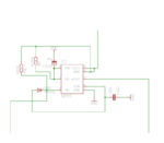
The time is at 55 sec .

I want from the circuit:
When the triger is activated after the activate the output be on for 50 sec.
For example if the triger is on for 20 sec. The output should be for 20+50 sec.
If i activate the triger for 5 secs then to stop activate the triger for 20 sec then again for 10 sec activate the triger , the ouput should be for 5+20+10+50.
Like a delay off din rail relay

My problem with this scematic is that some times it works sometimes not

Any help?
 

Hi,

Danger! You don't care about the minimum distances between mains voltage and isolated low voltage (SELV?).

You risk to hurt yourself and others!

Therefore I don't want to comment the rest.

First learn how to work with dangerous voltages.

Klaus
 
Putting the very real safety issues aside, a timing resistor of 8M with as timing capacitor of 10uF is bound to cause problems. I'm not sure what D555 is supposed to do either.
If you need accurate timing I suggest you look at other methods. Please observe what Klaus tells you, that layout is not really safe.

Brian.
 

Thanks for your help. This is a prototype pcb i just test the schematic. I am going to make a new PCB.
 

Hi,

Good news.
I am going to make a new PCB.

Besides safety issues...
Use a GND plane on your secondary side. Use bulk capacitor and decoupling capacitors on VCC.
Place your parts intelligent for short wiring with less crossings.
Read about EMI / EMC rules and folow them. Especially for all inputs and outputs.

Klaus
 
Dear all,
I design a new PCB.Untitled.png
Do you think is ok now. Is it safe?
The circuit works nice. Can someone post the EMC/EMI rules?
Thanks
 

Hi,

that is an improvement. Well done.

Is it safe? It depends on climatical influence, dirt, the voltages and the usage. And for sure the safte regulation of your country.

If you turn C1 90°, then you could make GND plane smaller and thus the distance to mains voltage wider. Also you could shift the 45° mains traces a bit to the left.
Mind: You don´t need that much distance between mains and mains. But you need more distance between mains and SELV for safety reasons.

The mains traces at the edge of the PCB is not nice, but if you put then PCB in a plastic box it should be OK.

Check if it is possible to change the 1N400x into 1N4148, they are much faster.

Can someone post the EMC/EMI rules?
At least in Germany this is very expensive. Buy a hundred sheets of paper and pay some hundreds of €.
Copying and sending is not allowed - at least in Germany, but i think in other countries also.

EMI/EMC rules depend on country.

****

Besides the EMI/EMC rules there are the safety rules. This is a more huge document and even more expensive. And it is hard to read and to understand...

Klaus
 
Dear all,
I design a new PCB.View attachment 119773
Do you think is ok now. Is it safe?
The circuit works nice. Can someone post the EMC/EMI rules?
Thanks

Due to surface leakage from dust and moisture, your design violates the creepage requirements for isolation in any country.

Have you tested it for 3kV Hipot yet?

Much more work needed to this design to make it reliable , safe and have no unintended radiation.
 

    V

    Points: 2
    Helpful Answer Positive Rating
Hi,

@OP
What is your module for? Industrial/commercial? voltage? in a case? What about dirt, temperature and humidity? Handheld or mounted?

@SunnySkyguy
Due to surface leakage from dust and moisture, your design violates the creepage requirements for isolation in any country.
What values do you suggest?
Are you referring to UL840 or UL508?
...
To me it seems that creepage is about 3mm. If not enough, then it should be not far away.

Klaus
 

    V

    Points: 2
    Helpful Answer Positive Rating
Dear all,
Thanks for you answers.
This module is for my home. I am going to put it in a plastic DIN-rail box into my electrical panel. The use of the board is when i am going to close the 1-3 contact(right) a contactor is going to activate all my home and when i am going to close the 4-5 contact with a magnetic reed switch the air condition line is going to activate (That is the reason i need the delay). The input voltage is 230vac-50hz. My panel do not have dust.
What is UL840 or UL508?
 

Hi,

What is UL840 or UL508?
These are safety standards. You may google for it.

If you have access, then read through UL840. Or read related documents.

Klaus
 
Status
Not open for further replies.

Part and Inventory Search

Welcome to EDABoard.com

Sponsor

Back
Top