Continue to Site

Welcome to EDAboard.com

Welcome to our site! EDAboard.com is an international Electronics Discussion Forum focused on EDA software, circuits, schematics, books, theory, papers, asic, pld, 8051, DSP, Network, RF, Analog Design, PCB, Service Manuals... and a whole lot more! To participate you need to register. Registration is free. Click here to register now.

'N' Steps And Stop Circuit (CD4017) Help

Status
Not open for further replies.

l2adiant

Junior Member level 1
Joined
Apr 17, 2013
Messages
15
Helped
0
Reputation
0
Reaction score
0
Trophy points
1,281
Activity points
1,375
hello guys i found a circuit below but that doesnt work exactly,
i want to make it, like, it should ON/OFF relay 4 times and then stop until i cut power
plz can any explain it and make it properly??? or any software simulation????

LM555StepStop.GIF


here is actual circuit but i want to reduce it to upper one to make it short n easy
**broken link removed**
 

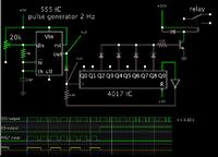
This screenshot shows a simulation for a similar request a few months ago.

It uses a 555 and 4017, in a similar fashion as your diagram.


This screenshot shows a simulation for a similar request a few months ago.

It uses a 555 and 4017, in a similar fashion as your diagram.


Can you please upload the simulation file?
 
Last edited by a moderator:

Clicking this link will open the website www.falstad.com/circuit, load my schematic, and run it on your computer.

https://tinyurl.com/myk55o3

To re-run the simulation, click the Reset button.

When you click Export a window opens containing the data file. I do not believe it is in Spice format.
 

i made this on vero board, my 555 pulse generator is working fine, as i place LED there, and its blinking properly, but the 4017 part doesnt work like it showing in simulator plz help

- - - Updated - - -

here is what i did, but the LED, ALWAYS keeps ON :(
and the led attached with the output of 555 is working fine, blinking continuously
Capture.PNG
 

The 4017 has a Reset pin which must have either 0V or supply V applied to it. It cannot be left unconnected.

Your schematic shows no wire going to the Reset pin.

By the way, I realize my simulation has no supply or ground going to the 4017. This is to simplify the layout. It is okay that your simulation shows a supply and ground connection.
 

Status
Not open for further replies.

Part and Inventory Search

Welcome to EDABoard.com

Sponsor

Back
Top