Continue to Site

Welcome to EDAboard.com

Welcome to our site! EDAboard.com is an international Electronics Discussion Forum focused on EDA software, circuits, schematics, books, theory, papers, asic, pld, 8051, DSP, Network, RF, Analog Design, PCB, Service Manuals... and a whole lot more! To participate you need to register. Registration is free. Click here to register now.

My RTC is ds1307 not work

Status
Not open for further replies.

PA3040

Advanced Member level 3
Joined
Aug 1, 2011
Messages
883
Helped
43
Reputation
88
Reaction score
43
Trophy points
1,308
Activity points
6,936
Dear All,

My RTC is ds1307
my pic is 16f877a

compiler Hi-Tech C

It is working fine for Proteus but it dose not work for my actual hardware please advice

Thanks in advance
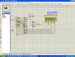
Code:
#include <htc.h>
#define _XTAL_FREQ 4000000 // 4 MHz clock 

__CONFIG(0X3F39);

#define LCD_EN RB3
#define	LCD_RS RB5
#define	LCD_RW RB4
#define LCD_DATA	PORTD
#define	LCD_STROBE()	((LCD_EN = 1),(LCD_EN=0))
unsigned char date [5] = {'D','a','t','e',':'};
unsigned char time [5] = {'T','i','m','e',':'};
unsigned char I2CData[8] = {0x00 , 0x00, 0x00, 0x01, 0x01, 0x01, 0x09, 0x00};
unsigned char tmp;

void I2CInit(void){
        TRISC3 = 1;      	/* SDA and SCL as input pin */
        TRISC4 = 1;      	/* these pins can be configured either i/p or o/p */
        SSPSTAT |= 0x80; 	/* Slew rate disabled */
        SSPCON = 0x28;   	/* SSPEN = 1, I2C Master mode, clock = FOSC/(4 * (SSPADD + 1)) */
        SSPADD = 0x28;    	/* 100Khz @ 4Mhz Fosc */
}

void I2CStart(){
        SEN = 1;         	/* Start condition enabled */
        while(SEN);      	/* automatically cleared by hardware */
                     		/* wait for start condition to finish */
}

void I2CStop(){
        PEN = 1;         	/* Stop condition enabled */
        while(PEN);      	/* Wait for stop condition to finish */
                     		/* PEN automatically cleared by hardware */
}

void I2CRestart(){
        RSEN = 1;        	/* Repeated start enabled */
        while(RSEN);     	/* wait for condition to finish */
}

void I2CAck(){
        ACKDT = 0;       	/* Acknowledge data bit, 0 = ACK */
        ACKEN = 1;       	/* Ack data enabled */
        while(ACKEN);    	/* wait for ack data to send on bus */
}

void I2CNak(){
        ACKDT = 1;       	/* Acknowledge data bit, 1 = NAK */
        ACKEN = 1;       	/* Ack data enabled */
        while(ACKEN);    	/* wait for ack data to send on bus */
}

void I2CWait(){
        while ( ( SSPCON2 & 0x1F ) || ( SSPSTAT & 0x04 ) );		/* wait for any pending transfer */

}

void I2CSend(unsigned char dat){
        SSPBUF = dat;    		/* Move data to SSPBUF */
        while(BF);       		/* wait till complete data is sent from buffer */
        I2CWait();       		/* wait for any pending transfer */
}

unsigned char I2CRead(void){
        unsigned char temp;
								/* Reception works if transfer is initiated in read mode */
        RCEN = 1;        		/* Enable data reception */
        while(!BF);      		/* wait for buffer full */
        temp = SSPBUF;   		/* Read serial buffer and store in temp register */
        I2CWait();       		/* wait to check any pending transfer */
        return temp;     		/* Return the read data from bus */	
}

void lcddata(unsigned char value)
	{
LCD_DATA = value;
LCD_RS = 1; 
LCD_RW = 0;
LCD_EN = 1;
__delay_ms (1);
LCD_EN = 0;

	}

void lcdcmd(unsigned char value)
	{
LCD_DATA = value;
LCD_RS = 0;
LCD_RW = 0;
LCD_EN = 1;
__delay_ms (1);
LCD_EN = 0;
	}

void bcdToascii(unsigned char value){

	tmp = value;
	tmp = tmp & 0xf0;
	tmp = tmp >> 4;
	tmp = tmp | 0x30;
	lcddata(tmp);
	tmp = value;
	tmp = tmp & 0x0f;
	tmp = tmp | 0x30;
	lcddata(tmp);

}
//-------------------------------------
void display (){
lcdcmd(0x80);
for (char i=0;i<5;i++)
			{
		lcddata(time[i]);
			}
	bcdToascii(I2CData[3]);
	lcddata('-');
	bcdToascii(I2CData[2]);
	lcddata('-');
	bcdToascii(I2CData[1]);
	
	lcdcmd(0xc0);
for (char j=0;j<5;j++)
			{
		lcddata(date[j]);
			}
	bcdToascii(I2CData[5]);
	lcddata('-');
	bcdToascii(I2CData[6]);
	lcddata('-');
	bcdToascii(I2CData[0]);
}

//-------------------------------------
void lcd_init(){
TRISD	= 0;
TRISB	= 0;
LCD_EN =0;
__delay_ms(175);
lcdcmd(0x38);
__delay_ms(175);
lcdcmd(0x0e);
__delay_ms(15);
lcdcmd(0x01);
__delay_ms(10);
lcdcmd(0x06);
__delay_ms(10);
lcdcmd(0x80);
__delay_ms(10);
lcdcmd(0x0c);
__delay_ms(10);
			}
//-------------------------------------
void main ()
{
 lcd_init();
	while(1){
		i2c();
		display();
			}

}
i2c(){
       
        I2CInit(); 						/* Initialize I2C Port */
       	I2CStart(); 					/* Send Start condition */
       	I2CSend(0xD0); 					/* Send DS1307 slave address with write operation */
		I2CAck();
        I2CSend(0x00);					/* Send subaddress 0x00, we are writing to this location */
		I2CAck();
        I2CRestart();					/* send slave address with read bit set */
        I2CSend(0xD1);					/* Loop to read 8 bytes from I2C slave */
		I2CData[0]=I2CRead();
		I2CAck();
		I2CData[1]=I2CRead();
        I2CAck();
		I2CData[2]=I2CRead();
		I2CAck();
		I2CData[3]=I2CRead();
		I2CAck();
		I2CData[4]=I2CRead();
		I2CAck();
		I2CData[5]=I2CRead();
		I2CAck();
		I2CData[6]=I2CRead();
		//I2CNak();
		I2CStop();						/* Send stop */
        								/* end of program */
		}

i2c_hitech c.JPG
 
Last edited:

Not worked RTC in hardware or not worked LCD?
You can debug project throw USART.
 
  • Like
Reactions: PA3040

    PA3040

    Points: 2
    Helpful Answer Positive Rating
if you leave the bat pin unconnected it may not work correctly.
I think that you should ground it if you are not using battery, check the datasheet
 
  • Like
Reactions: PA3040

    PA3040

    Points: 2
    Helpful Answer Positive Rating
One issue you maybe experiencing is the floating Vbat pin:

Reference: MAXIM DS1307 64 x 8, Serial, I2C Real-Time Clock Datasheet, Section: Pin Description, Page: 6

Vbat

Backup Supply Input for Any Standard 3V Lithium Cell or Other Energy Source. Battery
voltage must be held between the minimum and maximum limits for proper operation. Diodes in series
between the battery and the VBAT pin may prevent proper operation. If a backup supply is not
required, VBAT must be grounded.
The nominal power-fail trip point (VPF) voltage at which access to
the RTC and user RAM is denied is set by the internal circuitry as 1.25 x VBAT nominal. A lithium
battery with 48mAh or greater will back up the DS1307 for more than 10 years in the absence of power at +25°C.

Therefore, ensure the Vbat is tied to GND.

Other possible issues are ensuring proper values for the I2C pullup resistors and an appropriate crystal with proper load capacitance.

Also have you successfully utilized the LCD routines in previous projects?

LCD routines can be the source of numerous issues.


BigDog
 
Dear Bigdog and alex

Thanks for reply
I tied the Vbat pin to GND, unfortunately the problem remaining unchanged
I also change pullup resisters to 2.2k and 4.7k and 10k same result
and removed the RTC and power up and then the LCD displayed ??-??-??

what will be next step
please advice

- - - Updated - - -

Dear sarge,

Thanks for reply
You can debug project throw USART.

Can you please explain more how debug using USART, I have no idea how do that

Thanks in advance
 

Have you tried enabling the SQW output at 1Hz to check if you get pulses?
 
  • Like
Reactions: PA3040

    PA3040

    Points: 2
    Helpful Answer Positive Rating
Dear Alex
Thanks for reply

I think you mean write the value hex 10 to the address of 07 of RTC
Am I correct

rtc.JPG

Please help
 

Mr. PA3040,

You have to set date and time first before read something from the RTC.
 
  • Like
Reactions: PA3040

    PA3040

    Points: 2
    Helpful Answer Positive Rating
Dear papunbig
Thanks for reply
can we read what is the available data from TRC without write to it?
I think RTC starts to increment second when we power up it

Please advice
 

Dear Alex
Thanks for reply
I modified the source code as follows Am I correct ?
Code:
i2c(){
       
        I2CInit(); 						/* Initialize I2C Port */
       	I2CStart(); 					/* Send Start condition */
       	I2CSend(0xD0); 					/* Send DS1307 slave address with write operation */
		I2CAck();
		I2CSend(0x07);
		I2CAck();
		I2CSend(0x10);	
        //I2CStop();						/* Send subaddress 0x00, we are writing to this location */
		I2CAck();
        I2CRestart();					/* send slave address with read bit set */
        I2CSend(0xD1);					/* Loop to read 8 bytes from I2C slave */
		//I2CAck();
		I2CData[0]=I2CRead();
		I2CAck();
		I2CData[1]=I2CRead();
        I2CAck();
		I2CData[2]=I2CRead();
		I2CAck();
		I2CData[3]=I2CRead();
		I2CAck();
		I2CData[4]=I2CRead();
		I2CAck();
		I2CData[5]=I2CRead();
		I2CAck();
		I2CData[6]=I2CRead();
		I2CNak();
		I2CStop();						/* Send stop */
        								/* end of program */
		}
 

May be your crystal gets damaged..
as we need accurate crystal value for this...


Code:
I2CStart(); 					/* Send Start condition */
       	I2CSend(0xD0); 					/* Send DS1307 slave address with write operation */
		I2CAck();
		I2CSend(0x07);
		I2CAck();
		I2CSend(0x10);	
        //I2CStop();						/* Send subaddress 0x00, we are writing to this location */
		I2CAck();
        I2CRestart();					/* send

Yes this should set the output to 1Hz

- - - Updated - - -

I haven't used the chip for a while but I remember correctly if you don't set time it starts from 00:00
 

Hi PA3040;

From the 1307 datasheet:
Please note that the initial power on state of all registers is not defined. Therefore it is important to enable the oscillator (CH bit=0) during initial configuration.Bit 7 of Register 0 is the Clock Halt (CH) bit. When this bit is set to a 1, the oscillator is disabled. When cleared to a 0, the oscillator is enabled.

So first (at start) read only the 0 register (sec) and check the CH bit (7th).
Only if it is equal to 1 then set all registers as you want (to init time, with sec=0) else do nothing, the clock is already running!

In Proteus always use DIGITAL (and not ANALOG) pullup I2C resistors!
 
  • Like
Reactions: PA3040

    PA3040

    Points: 2
    Helpful Answer Positive Rating
Dear suisti
Thanks for reply

please look at the following codes. Am I correct?


Code:
I2CInit(); 						/* Initialize I2C Port */
       	I2CStart(); 					/* Send Start condition */
       	I2CSend(0xD0); 					/* Send DS1307 slave address with write operation */
		I2CAck();
		I2CSend(0x00);
		I2CAck();
[COLOR="#FF0000"]I2CSend(0x00); //clock halt (CH) bit[/COLOR]

Thanks in advance
 

It is fine for testing but note that this sets the seconds to 0 so if the timer was already working then this would mess the seconds.

Read address 0 and check bit 7, if it is 1 then write 0 to address 0
 

Dear All,
I improved a bit forward. Now it reads second location only it dose not read minute location and onwards
it is running Both Proteus and my hardware
when I insert I2CAck() function after every reading the operation totally out

can any body have advice
Thanks in advance
 

Is the value of bit7 in address0 =0 when you check it?
 
  • Like
Reactions: PA3040

    PA3040

    Points: 2
    Helpful Answer Positive Rating
Status
Not open for further replies.

Similar threads

Part and Inventory Search

Welcome to EDABoard.com

Sponsor

Back
Top