André Ferrato
Newbie level 3

Hello guys, this is my first post in this forum. I recently started making a rf rc car, as you may see it is a very simple project that i designed the pcbs in eagle and took some circuit from the web. I would like to ask some questions about my concerns at the moment.
1) I intend to use a 7.5v battery pack to run the receiver board, but i'm afraid of the drop that will occur inside the L293D chip, will it be a large drop using this motors ?
2) I am using a 10uF electrolytic aluminum capacitor at the input of the LM7805 and a 100nF ceramic capacitor on the output, i think it's a nice setup, is it ?
3) Also i am using a few jumper wires in the board, would it be good to connect 100nF ceramic capacitors near to those pins ? I am aware they will be acting like little antennas, but i dont know if the effect will something i need to consider in this project.
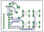
4) I faced some difficulties while routing the receiver board and i think this design i reached is a very poor design, if anyone could give me some tips and help it would be nice.
5) Is there anything i should add to these designs ? I am new to electronics.
PS: I know some pads are larger, some vias are larger, but this is just for making the manufacturing of the board easier. I have done it before and helped a lot. Also i am tied up to these devices, i can't change the motor drive or the encoders/decoders/rf modules.
Transmitter Diagram

Transmitter Board #1

Transmitter Board #2
View attachment J38rJyM.png
Receiver Diagram

Receiver Board #1

Receiver Board #2
View attachment Q6mzMGm.png
Motor data chart

I attached the eagle files if anyone wanna take a closer look.
1) I intend to use a 7.5v battery pack to run the receiver board, but i'm afraid of the drop that will occur inside the L293D chip, will it be a large drop using this motors ?
2) I am using a 10uF electrolytic aluminum capacitor at the input of the LM7805 and a 100nF ceramic capacitor on the output, i think it's a nice setup, is it ?
3) Also i am using a few jumper wires in the board, would it be good to connect 100nF ceramic capacitors near to those pins ? I am aware they will be acting like little antennas, but i dont know if the effect will something i need to consider in this project.
4) I faced some difficulties while routing the receiver board and i think this design i reached is a very poor design, if anyone could give me some tips and help it would be nice.
5) Is there anything i should add to these designs ? I am new to electronics.
PS: I know some pads are larger, some vias are larger, but this is just for making the manufacturing of the board easier. I have done it before and helped a lot. Also i am tied up to these devices, i can't change the motor drive or the encoders/decoders/rf modules.
Transmitter Diagram

Transmitter Board #1

Transmitter Board #2
View attachment J38rJyM.png
Receiver Diagram

Receiver Board #1

Receiver Board #2
View attachment Q6mzMGm.png
Motor data chart

I attached the eagle files if anyone wanna take a closer look.
Attachments
Last edited by a moderator:


