Vermes
Advanced Member level 4

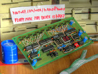
This system receives MIDI signal and controls 16 floppy drives. MIDI input is carried out via a serial port. This solution can be improved by implementation of a current loop through which you can select whether the signal is to be taken from the real MIDI or from MIDI on RS232.
There are 16 4-pin outputs, each for one drive. The floppy drives 5,25-inch do not differ from these 3,5-inch. Every output uses 4 wires: 2 for controlling the head, one for the diode and switching on the drive and one return wire, through which the drive informs when the head is on the first path.
Device is also equipped with EEPROM memory and I2C output for further development. There is also an output for display HD44780 or compatible display. Four digits consist of 7-segments. They are controlled by UAA2022.
The entire system is controlled by Atmega8A. Floppy disks are plugged through shift registers. The control program actualizes the position of a floppy drive with a frequency of about 15kHz. Each drive corresponds to one MIDI channel. Unfortunately, it can play only one sound at once.
All the necessary MIDI messages were programmed:
- Note on – when a sound is played, it fades and a new sound is played
- Note off – it works as Note on with volume = 0
- All sound off and All notes off – floppy drives are switched off
- Device reset – floppy drives are switched off
- Realtime command – when it occurs during the normal time, the device does not break
- Active sensing – when it is received as the first command, when the next is not received within 1s, the drives fade
- Pitch bend
- Running status – controlling device does not have to reply the byte status if it is identical with the previous one
HD44780 is connected through a shift register, while MSB bit is connected directly to the mcu so that it is possible to read the busy flag, R/W is also connected to /OE in the register, to disable the register outputs when the LCD is allowed to play. All the wires are common with the floppy registers outputs. The only exception is the E wire from the LCD, because while inserting anything to the floppy disks, you could possibly send unwanted content to the LCD.
Buttons are also connected through a shift register PISO. There is an additional wire responsible for reading.
Another peripheral is UAA2022, it is a SPIO register with current outputs for LEDs. It has an additional one wire from the mcu on the input that latches the register to outputs. Unfortunately, UAA2022 has a bad AC characteristic, so that it was programmed to allow inserting one bit while sending all to the drive (15kbit/s). The clock wire is shared with the latch on the floppy and at on the clock from the LCD. During an interrupt, 16 bits are inserted to the LCD and latched (inserting 1 bit to the UAA at the same time). Next, after the interrupt, the program provides inserting to the LCD, so theoretically, 8 times floppy disks are latched at once, but their internal content does not change and nothing happens. UAA2022 has a characteristic that it does not respond to short pulses while inserting to the LCD.
The system is also equipped with 4 multiplexed digits, 2 pins for controlling dots (plugged through pnp to the common anodes).
PCB:
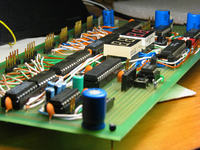
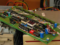

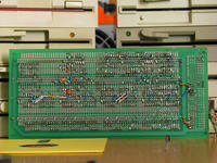
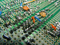
Building the circuit, bases on MAX232, Atmega8A and floppy registers:
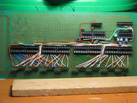
Circuits:
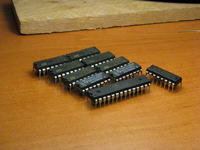
Tests:
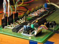
Circuit working:
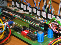
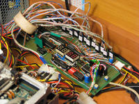
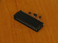
Socket for 5-inch drive:
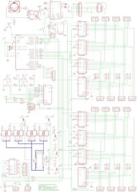
Schematic:
Video:
Link to original thread - Muzyczne stacje dyskietek - 16-kanałowy sterownik MIDI