Continue to Site

Welcome to EDAboard.com

Welcome to our site! EDAboard.com is an international Electronics Discussion Forum focused on EDA software, circuits, schematics, books, theory, papers, asic, pld, 8051, DSP, Network, RF, Analog Design, PCB, Service Manuals... and a whole lot more! To participate you need to register. Registration is free. Click here to register now.

Multiplexing relay states through a single wire

Status
Not open for further replies.

kathmandu

Full Member level 5
Full Member level 5
Joined
Dec 7, 2015
Messages
298
Helped
7
Reputation
14
Reaction score
7
Trophy points
18
Activity points
3,146
Hello,

I want to connect the outputs of 6 motion sensors to a uC input through a single wire (along with the 12VDC/GND wires).

The motion sensor's outputs are solid state (normally closed) but I could use some miniature relays to get NO/NC if that helps.

I thought of using a distributed binary weighted resistor network and a current source at the uC side.

This way, every relay (motion sensor) puts a series (or parallel) resistor in circuit thus I'll get different voltage readings at uC side (ADC) depending on what motion sensors (one or multiple) are active.

Is there any other simple way to accomplish this?
 

Hi,

Other methods:
* time_multiplexed. 1 of 8 decoder for example.
* priority encoder: 8 inputs, 3(+1) outputs
* I2C expander. 8 inputs with interrupt capability (two wires)
* 6 inputs at your receiving device. (you keep as secret?)
* 6 different frequencies generated.
* 6 different LC resonant filters
* one wire digital protocol

Klaus
 
Many thanks, Klaus, but all those methods seems more complicated.

The motion sensors are placed on different locations and I don't want to run a separate cable (star connection) form each sensor to the uC or to any other multiplexing circuit.
 

Is there any other simple way to accomplish this?

A weighted resistor network (not necessarily binary) seems a nice approach in terms of simplicity, but may have limitations in regard to the maximum resolution achieved without affected by noise, and the proper cabling selection (shielded) is the factor determinant to be successful.
 
The window comparator might work for you. A 3914 IC distinguishes 10 volt levels. You would need to adjust output from each motion sensor so it occupies its own unique window.

Suppose you adjust the 3914 so its outputs step up or down in response to incoming signals one volt apart.
You adjust motion sensor #4 so that it sends 4 V.
When it turns on, it sends a 4V signal to the 3914, causing pin #4 to change state.

This assumes only one sensor turns on at any one time.
 

Yes, I need to know which one is active to turn on a corresponding light, to activate a webcam and so on.

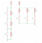
I guess I have to choose between these two topologies (series or parallel):

weighted-resistor.png

As for the series topology it's quite simple to calculate the resistors to get constant voltage steps (by using binary sized resistors: R, 2R, 4R and so on), I don't know what's the best choice for the parallel resistors (as the equivalent resistor is quite a nonlinear function).

Do you know what's the best choice for these resistors (parallel topology) as it seems easier to implement/extend?

- - - Updated - - -

@BradtheRad:

I have a 12bit ADC (3.3V) to read that voltage thus it could sense quite small voltage steps (though I don't need more than 6 different voltage steps anyway).

=====

LATER EDIT: Actually, I need to check 2^6 (64) voltage steps.
 
Last edited:

if you are not worrying if two or more detector's will get activated SIMULTANEOUSLY prefer the parallel method , and change detector to N.O. (its simpler)

if more than one is going to get activated at the same time , resistor method for more that 2(3?) gets really complicated at calculation level imho
and a digital method should prefered (i2c, onewire etc)
 

I did some calculations with R, 2R, 3R, ... (parallel resistors) and I got acceptable voltage thresholds.

I'll run some calculations with R, 4R, 8R, ... (by example) to check for any improvements.

- - - Updated - - -

Btw, to clarify this: every motion sensors could activate independently and I need to know exactly which one (or ones) becomes active at any moment.

For the series topology, there should be no problems with 6 binary resistors (1K, 2K, 4K, 8K, 16K and 32K, by example).

at what tolerance you would work ? 5,2,1 % ? and what tolerance cable, future cable influence will have ?
If you work, even, at 5% tolerance, resistor value it self would be 30.4 - 33.6. Therefore 1K and 2K values, simultaneously activated, it is inside error level !

You need at least 1% resistor's AND even then if 2-3 resistor's activated simultaneously, its inside correct levels, but risky. As you also have cable run and possible external noise.
However it is possible to oversample it and calculate error via software average rates.

and these values is with series resistor in mind, parallel resistor is even more stricter in calculation
 
Last edited:
1℅ resistors are very common. To avoid the noise effect, I could use a higher current, to get 12VDC at full scale then I use a voltage divider at uC side to get 3.3VDC (full scale) to feed the ADC input.

So, for 12VDC and 64 steps (actually, 63) I'll get a voltage step of 190 mV. I have one twisted pair shielded cable available (the shield will be used as ground) thus I don't think I'll have any problems with the noise margin.

- - - Updated - - -

You're right, a parallel topology might be overkill.
 

Hi,

I'd use the serial connection.
R, 2R, 4R...
And a constant current source.

* The constant current source makes the readings linear. This makes it easy to detect the activated sensors.
* And with the serial connection you may detect a broken wire. This gives additional safety.

Klaus
 

I like Klaus's constant current approach. It allows you to use the NC grounded outputs in a series configuration with linear steps.
Here's my take on that--
Connect a R, 2R, 4R... resistor in series with each of the NC sensor output (say 100, 200, 400,... 3.2k), all connected to one line.

Use a constant current source (such as an LM317 CC circuit) to drive the line and generate a suitable full scale voltage (say 3.125mA for 10V with all outputs open except the 3.2k) .
The minimum voltage (all outputs closed) would be then be 156mV.

An 8-bit or higher A/D converter should be able to readily resolve all 64 voltage levels with 156mV steps between those two extremes.
Then you just have to binary map the voltage into which sensors are activated.

1% resistors should give you sufficient accuracy for that purpose.

You could also sense if any sensor is activated by using a comparator to detect if the voltage goes above about 200mV.
 
Many thanks for your confirmation. As I did mention in my first post (and drawn in the above schematics):

I thought of using a distributed binary weighted resistor network and a current source at the uC side.

.. I was talking about a current source, too.

Anyway, the next best method (as mentioned above) is to use some 1-wire chips (e.g. DS2413, dual channel addressable switch).

This way, you can freely expand/modify the network at any time and you get an extra input (tampering detection) or output (enabling local alarm or warning lights).

For now, I'll test the weighted resistor network method but I will surely update it to 1-wire protocol (as I already have such a network configured at MCU level for some temperature sensors).
 

Status
Not open for further replies.

Similar threads

Part and Inventory Search

Welcome to EDABoard.com

Sponsor

Back
Top