Continue to Site

Welcome to EDAboard.com

Welcome to our site! EDAboard.com is an international Electronics Discussion Forum focused on EDA software, circuits, schematics, books, theory, papers, asic, pld, 8051, DSP, Network, RF, Analog Design, PCB, Service Manuals... and a whole lot more! To participate you need to register. Registration is free. Click here to register now.

[51] Multiplexing 7 segment display

Status
Not open for further replies.

Ma3ix

Member level 2
Member level 2
Joined
Dec 17, 2015
Messages
43
Helped
0
Reputation
0
Reaction score
0
Trophy points
6
Activity points
375
Hello,

im working on my project and I have to display output data on multiplexed 7 segment display with common cathode. MCU is AT89S51. I have doubt will something like this work?
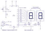
multiplexing-7-segement-display-to-8051.png
https://www.circuitstoday.com/wp-content/uploads/2012/06/multiplexing-7-segement-display-to-8051.png

Can MCU AT89S51 source current approx 20mA to drive the displays?

Thanks
 

I have doubt will something like this work?

Can MCU AT89S51 source current approx 20mA to drive the displays?

In fact, a resistor of 560R would limit the maximum current for something near to 8mA. I suspect that the intrinsic 51's inner pullup resistors would also reduce the current a few more. You could add some ULN2003 IC just to ensure a sufficient driving capability.
 

Thanks for answer. Then I could just put smaller resistor, if segment need 2V, then the R = 3V/0.02A -->150 Ohms..
Will this work? DO I need ULN2003..
And why somebody put PNP transistor on each segment of display (before current resistor of segment led) if MCU 8051 can supply display with just putting the resistors on each pin?:idea:
 

:thumbsup::thumbsup:
You should use 220 ohm or 330 ohm resistors for 7 segment displays. And 10 kohm for those transistor.
It works try it....
 

Im in doubt cause in this tutorial at 20:00 https://www.youtube.com/watch?v=Lsq635rn7j0 guy said that we must use transistor for segment drive cause 8051 MCu cannot source current? Can somebody explain me why he insist of using transistor on segments ..

In my 1st post, the segment and digit select will both work with pins of MCU selected high?
 

It depends what you intend to use the displays for. If it's for an alarm clock to be used at night for example, only a few mA will be sufficient to make the displays light up, thus you'll be able to drive them directly from the MCU without a problem. If you want to use them in a very bright environment however, you might need 15+ mA which the MCU can't source or sink directly, and then a buffer like the ULN2003 or discrete transistors are required.
 

Ok thanks;-). I thought I could achieve necessary source current for display just using the Ohm law (5V volts and required current resistor to get current I need.. :/). In datasheet of at89S51 I did not find anything related for max source current on pins..? They are just mentioned max sink current what is something i dont need in my case.

So, if full bright segment need about 20mA, and with this solution I cant get "bigger" current than >5mA then i could use smallest resistor I have for segments?
 

I thought I could achieve necessary source current for display just using the Ohm law (5V volts and required current resistor to get current I need

To be exact, the kirchoff law is what you will use, because the drop voltage across the LED segment should be accounted, which is also depentent of the color of the LED.

So, if full bright segment need about 20mA, and with this solution I cant get "bigger" current than >5mA then i could use smallest resistor I have for segments?

You did not mentioned yet the P/N of the 7-seg display device; there are variants offering high brigh with smaller currents.
 
  • Like
Reactions: Ma3ix

    Ma3ix

    Points: 2
    Helpful Answer Positive Rating
To be exact, the kirchoff law is what you will use, because the drop voltage across the LED segment should be accounted, which is also depentent of the color of the LED.


You did not mentioned yet the P/N of the 7-seg display device; there are variants offering high brigh with smaller currents.


I use SC52-11EWA 7 segment display.

If I use transistor bc337 for switching displays, what values do I have to use in calculations for base resistor? In that tutorial guy said that max current on collector is Ic= 8 x (current on each segment of display) , to get Ib he uses Ib = Ic / hfe.. Is that good approach?
For example if i use 10k resistor with bc 337 i get Ib arround 0.5 mA, would be that enought for turning on the display :/
 
Last edited:

In datasheet of at89S51 I did not find anything related for max source current on pins..?
Don't believe you read it thoroughly. Consider the meaning of Voh and Iil specifications. Source current is a few 10 µA only.

In fact, 8051 can neither drive the segments nor BC548 or BC337 digit switch transistors.
 

Don't believe you read it thoroughly. Consider the meaning of Voh and Iil specifications. Source current is a few 10 µA only.

In fact, 8051 can neither drive the segments nor BC548 or BC337 digit switch transistors.

It is initial source current because its internal pull-ups. If I put external resistor and set pin high, by Ohms low I can get bigger current for driving the segment? Is that correct:thinker:
 

Yes, you can add external pull-ups to increase the high current, e.g. to drive a digit transistor. According to output drive capability and maximum ratings, a resistor values down to about 2.5k are feasible. You still need additional driver transistors for the segment lines.

Ok, thanks a lot. Im a begginer with MCU and I try not to burn devices with wrong configuration :D.

What is it about max DC output current of 15mA? Is that mean that sum of all source current on pins (in my example: 8 for segment + 3 for display select) must not be exceeded that value?
 

Yes, you can add external pull-ups to increase the high current, e.g. to drive a digit transistor. According to output drive capability and maximum ratings, a resistor values down to about 2.5k are feasible. You still need additional driver transistors for the segment lines.

- - - Updated - - -

It's specified as 15 mA per 8-Bit port.
 
  • Like
Reactions: Ma3ix

    Ma3ix

    Points: 2
    Helpful Answer Positive Rating
Thanks a lot. :thumbsup:
If I put PNP transistor to increase current for driving led, is this calculation for Rb and Rled good?
bc557.jpg
 

If I use uln2003A for driving segments instead of transistor how to estimate Rled? For logic 1, input in uln2003 would be : I= 10uA, V=5V, and how about output?
 
Last edited:

Status
Not open for further replies.

Similar threads

Part and Inventory Search

Welcome to EDABoard.com

Sponsor

Back
Top