Continue to Site

Welcome to EDAboard.com

Welcome to our site! EDAboard.com is an international Electronics Discussion Forum focused on EDA software, circuits, schematics, books, theory, papers, asic, pld, 8051, DSP, Network, RF, Analog Design, PCB, Service Manuals... and a whole lot more! To participate you need to register. Registration is free. Click here to register now.

Multiple varying delays to signals in VHDL

arifboy

Newbie
Newbie level 4
Joined
Mar 22, 2025
Messages
5
Helped
0
Reputation
0
Reaction score
0
Trophy points
1
Activity points
43
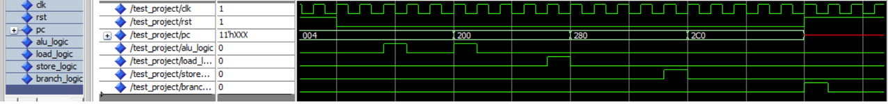
I am working on a VHDL code to insert multiple varying delays to signals. I have shown code below and expected waveforms and present waveforms respectively too. How can the code be changed to get desired waveforms?

Code:

int := conv_integer(pc);

wait until rising_edge(clk);

if (int >= 0 and int <= 500) then -- alu/j
load_logic <= '0';
store_logic <= '0';
branch_logic <= '0';
wait for 20 ns; alu_logic <= '1';
wait for 20 ns; alu_logic <= '0';


elsif (int >= 504 and int <= 600) then --load
alu_logic <= '0';
store_logic <= '0';
branch_logic <= '0';
wait for 40 ns; load_logic <= '1';
wait for 20 ns; load_logic <= '0';

elsif (int >= 604 and int <= 700) then -- store
alu_logic <= '0';
load_logic <= '0';
branch_logic <= '0';
wait for 60 ns; store_logic <= '1';
wait for 20 ns; store_logic <= '0';

else --- br/j
alu_logic <= '0';
load_logic <= '0';
store_logic <= '0';
wait for 80 ns; branch_logic <= '1';
wait for 20 ns; branch_logic <= '0';

end if;

right.png
wrong.png
 
What are you trying to achieve? If you are targeting to synthesizable HDL, timed wait statements must replaced by clocked timers. 10 ns resolution (100 MHz clock) should be no problem with recent FPGA or CPLD.
 
What are you trying to achieve? If you are targeting to synthesizable HDL, timed wait statements must replaced by clocked timers. 10 ns resolution (100 MHz clock) should be no problem with recent FPGA or CPLD.
In Simulations, the waveforms which I target must be possible, but I failed to get using both 'wait' and 'after' and even with combo of these two too. So maybe I am missing some key points. Synthesis can be achieved by a different approach, but first thing is Simulations and get the required behavior
 
Combination of wait_until rising_edge(clk) and wait for is most likely not achieving what you want.
I see two problems why the expected waveform (upper picture) isn't achieved:

1. wait for is blocking the whole process. Alternative cases aren't evaluated before the last active wait for has timed out.
2. your code has no means to generate a specific signal only once, it's not corresponding to expected waveform.

I would choose a different approach, delay generated by counting clock cycles. Having spearate timers for each signal, they can be generated independant of other timers. The code will be also synthesizable.
 
wait until rising_edge(clk);
Shows that this is a testbench use case!

You can use "wait" statements to wait for a specific amount of time.
To delay a signal before assigning it to some other signal at the testbench, you can use transport dealy modeling (e.g. sig2 <= sig1 after 7 ns).

But since it seems you are writing a test bench for some sequential logic (cpu, etc...). So I would highly advise you to write a testbench containing process statements which has the clock in the sensitivity list. You will have a lot of control and clear understanding of what is being done. I do not support the way you have written the TB to simulate your DUT.

Additionally - the advice given in the post above!
 
Last edited:
Shows that this is a testbench use case!

You can use "wait" statements to wait for a specific amount of time.
To delay a signal before assigning it to some other signal at the testbench, you can use transport dealy modeling (e.g. sig2 <= sig1 after 7 ns).

But since it seems you are writing a test bench for some sequential logic (cpu, etc...). So I would highly advise you to write a testbench containing process statements which has the clock in the sensitivity list. You will have a lot of control and clear understanding of what is being done. I do not support the way you have written the TB to simulate your DUT.

Additionally - the advice given in the post above!
This is program code, not the testbench. I was using after previously as you mentioned but second after nullifies first one for each of if else above. Wait actually is doing something at least, but output is not right one. I think its not possible to simulate it in this way in VHDL, at least by using the transport, after and wait given in language itself.
 
This is program code, not the testbench
Then just put this in the garbage bin (yes I am being this straightforward) and write fresh RTL code in which you have process blocks with sensitivity lists.
You must write synthesizable RTL code and there are rules to write synthesizable RTL code.
--- Updated ---

Synthesis can be achieved by a different approach, but first thing is Simulations and get the required behavior
This approach for logic design is also completely wrong!

You must FIRST write RTL code which is synthesizable and then write code for test bench, which will generate peripheral signals to verify your synthesizable code using behavorial simulation.

Nevertheless follow a good tutorial for RTL design and learn the basics first!
 
Last edited:
You need need the execution to happen only once during the frame. Declare checker and try this:

if (int >= 0 and int <= 500) then -- alu/j
checker <= '0'
load_logic <= '0';
store_logic <= '0';
branch_logic <= '0';
If checker = '0' then
wait for 20 ns; alu_logic <= '1';
wait for 20 ns; alu_logic <= '0'; checker <= '1';
end if;

Add checker to all cases in this way.

Here you're just using checker to get it to happen just once. If this doesn't solve it, then we will modify it to get it to work.
With your suggestion the waveform came closer to what the expected waveform is, but still not exactly there. I have attached a photo of that. You suggested if, I used while too with other lines exactly as you mentioned, but that didn't work too according to expectation.
 

Attachments

  • modified.png
    modified.png
    58.6 KB · Views: 6
Let's see your latest code then, and we can take a further look at it.
Its the same, I just added those lines of you with signal checker..Intiially there is extra cycle added as you see in waveform. It is taking an extra cycle instead of just one, to make Alu_logic a 1. You cant simulate it at your end?
--- Updated ---

Then just put this in the garbage bin (yes I am being this straightforward) and write fresh RTL code in which you have process blocks with sensitivity lists.
You must write synthesizable RTL code and there are rules to write synthesizable RTL code.
--- Updated ---


This approach for logic design is also completely wrong!

You must FIRST write RTL code which is synthesizable and then write code for test bench, which will generate peripheral signals to verify your synthesizable code using behavorial simulation.

Nevertheless follow a good tutorial for RTL design and learn the basics first!
You yourself dont know VHDL, thats why you suggested use of after statement. After statement gives inertial delay, but you think its transport delay. I have already told you after statement doesn't work for this program. You are just wasting time of both of us. Why dont you learn VHDL first, before telling me to learn it??
 
Last edited:


Write your reply...

LaTeX Commands Quick-Menu:

Part and Inventory Search

Welcome to EDABoard.com

Sponsor

Back
Top