Continue to Site

Welcome to EDAboard.com

Welcome to our site! EDAboard.com is an international Electronics Discussion Forum focused on EDA software, circuits, schematics, books, theory, papers, asic, pld, 8051, DSP, Network, RF, Analog Design, PCB, Service Manuals... and a whole lot more! To participate you need to register. Registration is free. Click here to register now.

[MOVED] Transition from PIC16F84 to PIC16F628A.

Status
Not open for further replies.

pnjbtr

Full Member level 5
Full Member level 5
Joined
Feb 11, 2008
Messages
255
Helped
99
Reputation
198
Reaction score
89
Trophy points
1,318
Activity points
2,815
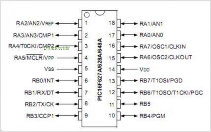
PIC16F628A is pin compatible with pic16f84.
I urge to migrate from pic16f84 to pic16f628a.
Only confusion is 16f628a have built in ADC, osc (internal) and
comparator.
Source code is in asm.
Any suggestion?
 

If you are upgrading from a PIC16F (or C) 84 (A) all the port pins are in the same positions on both chips. Port B is identical. Port A on the PIC16F84 has 4 in/out and 1 "input and "half-output". The PIC16F628 has 6 in/out, one "input and half-output" (RA4) and 1 input only (RA5).

The thing you have to remember is:
On both the PIC16F84 and PIC16F628, RA4 is an "input and half-output". When used as an output, these pins will only sink 25mA and source 0mA. To make the pin source, connect the base of a transistor to the pin and put the transistor in emitter-follower mode by connecting the collector to the positive rail as in the diagram below. RA5 on a PIC16F628 is input only.
 

Hi,

The 628A is a much better choice over the 84A with its on board 4Mhz oscillator and its Analogue Comparator - that is not ADC, Analogue to Digitial Converter, important difference.

Also look at the 16F88 chip, an even better chip, again pin compatible but has the advantage of several channels for the 10 bit ADC, an internal oscillator with several selectable frequencies up to 8 Mhz etc.
 
  • Like
Reactions: pnjbtr

    pnjbtr

    Points: 2
    Helpful Answer Positive Rating
Before i work with PIC16F72
And pin out display as AN0 AN1, pic16f72 have these pins with adc module.
When i see pin out of PIC16F628A.
45_1347739517.jpg

I see these pins 1, 2, 17, 18, also marked as AN0 - AN3.
according to data sheet of 16F628A, it do not have adc module.
We can use these pins as analog input.
Can we use these pin same as we use in PIC16F72.

Hi,

You need to read the datasheets a bit more -see the PINOUT DESCRIPTIONS near the begining of each datasheet.

AN0 are just general indicators - for the 628/A it indicates an Analogue Comparator, on the F88 and F72 they are Analogue inputs to the ADC function.

Basically the Analogue comparators takes two analogue signals and compares them, with a simple high or low result.

An ADC reads the 0v to 5v voltage present on the input pin and converts it into a digital value, from 0 to 1023 if its a 10 bit adc.

Why the sudden change to a 28 pin F72, thought you wanted to keep compatible with the old F84 ?

When selecting a chip ensure that the programmer you have can actually program the chip.
 
  • Like
Reactions: pnjbtr

    pnjbtr

    Points: 2
    Helpful Answer Positive Rating
Why the sudden change to a 28 pin F72, thought you wanted to keep compatible with the old F84 ?
Sorry,in my earlier post i mean to say i have experience of a code
writing for PIC16F72.
Now i am thinking F88 is just right,as you suggested.
PIC16F88 have adc module with 5 analog inputs.
 

Status
Not open for further replies.

Similar threads

Part and Inventory Search

Welcome to EDABoard.com

Sponsor

Back
Top