Continue to Site

Welcome to EDAboard.com

Welcome to our site! EDAboard.com is an international Electronics Discussion Forum focused on EDA software, circuits, schematics, books, theory, papers, asic, pld, 8051, DSP, Network, RF, Analog Design, PCB, Service Manuals... and a whole lot more! To participate you need to register. Registration is free. Click here to register now.

[Moved] need help on 2 Diode D1 and D2 250 to 5000 watts PWM Dc/Ac power Inverter

Status
Not open for further replies.

Rambo55

Banned
Member level 3
Joined
Oct 7, 2009
Messages
63
Helped
3
Reputation
6
Reaction score
1
Trophy points
1,288
Location
Australia
Activity points
0
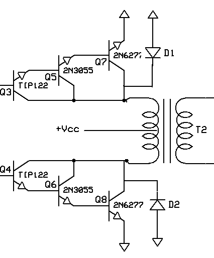
Need help on the 2 Diode D1 and D2 in the Schematic
 

Attachments

  • F6K45ZBFTY4CWZL.gif
    F6K45ZBFTY4CWZL.gif
    50.1 KB · Views: 104

Re: need help on 2 Diode D1 and D2 250 to 5000 watts PWM Dc/Ac power Inverter

Need help on the 2 Diode D1 and D2 in the Schematic
They are shorting the inverter and must not be there. Who has invented this circuit?

The designer probably meaned to limit transistor overvoltages. There are two possible means:
- anti-parallel diodes to the transistors to cut negative voltages, that can be brought up by inductive loads
- using (power) z-diodes instead of regular diodes anti-parallel to the transistors can additionally cut positive overvoltages above 2 -3 times the battery voltage
 

Re: need help on 2 Diode D1 and D2 250 to 5000 watts PWM Dc/Ac power Inverter

The diode are IN5407
 

Re: need help on 2 Diode D1 and D2 250 to 5000 watts PWM Dc/Ac power Inverter

The diode are IN5407
yes it is IN5407\IN5406
You mean, it's correct to connect diodes across a push-pull transformer?
 

Re: need help on 2 Diode D1 and D2 250 to 5000 watts PWM Dc/Ac power Inverter

You mean, it's correct to connect diodes across a push-pull transformer?
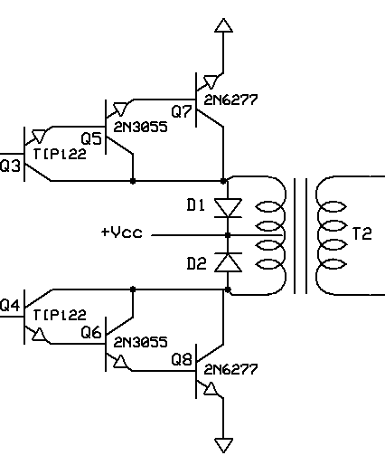
Yes those diodes are correct they are used to protect transistors from regenerative currents from Transformer during pulse of time. these diodes will short the reverse current and capable to withstand and protect remaining circuit.
 

Do you understand how a transformer works?

There are two options to protect the transistors against inductive kickback:
- connect reverse diodes between collector and emitter of the output transistors
- connect a Z-diode + rectifier diode series circuit across the transformer windings. Z diode voltage should be at least equal to the supply voltage.

wrong:

82_1318314554.gif


right:

11_1318314554.gif
 
Last edited:
Trust FvM. his solution is best !

Consider what happens when one side of the transformer is connected to ground via Q7 or Q8, see what the polaity of the OTHER winding does at the same time and how the diode across it conducts.

Incidentally, the driver circuit is VERY prone to leakage current, it effectively has four bipolar transistors in cascade, the slightest leakage in Q3/Q4 will be magnified many times by the overall gain. If Q3/Q4 were mounted on the same heatsink as Q7/Q8 there could be serious thermal runaway problems.

Brian.
 
  • Like
Reactions: FvM

    FvM

    Points: 2
    Helpful Answer Positive Rating
Incidentally, the driver circuit is VERY prone to leakage current, it effectively has four bipolar transistors in cascade, the slightest leakage in Q3/Q4 will be magnified many times by the overall gain.

I agree, that the design has other issues besides misplaced diodes.
 

Status
Not open for further replies.

Similar threads

Part and Inventory Search

Welcome to EDABoard.com

Sponsor

Back
Top