Continue to Site

Welcome to EDAboard.com

Welcome to our site! EDAboard.com is an international Electronics Discussion Forum focused on EDA software, circuits, schematics, books, theory, papers, asic, pld, 8051, DSP, Network, RF, Analog Design, PCB, Service Manuals... and a whole lot more! To participate you need to register. Registration is free. Click here to register now.

[Moved] IR pair circuit troubleshooting

Status
Not open for further replies.

phrbob93

Member level 1
Member level 1
Joined
Mar 28, 2014
Messages
38
Helped
0
Reputation
0
Reaction score
0
Trophy points
6
Location
Jalandhar, punjab
Activity points
343
i am following a circuit of ir pair which i have seen in many tutorials
the circuit is given in the picture..i did followed same as the circuit but i dont know why its not working..
will any one please look at my circuit and just let me know where iam wrong..
the led connected is supposed to be off when some obstacle is in front of ir pair...
but its keep in the on state upload 2.PNGupload1.jpgupload.jpg
 

Shouldn't the obstacle come in between the IR pairs? The way your IR transmitter and receiver are placed. The receiver will continuously receive and will conduct that's why LED is on All the time.

Move the LED pair away from one another and put an obstacle in between them to test your circuit.

In the present placement too you can try putting something (Black in Color if possible) between the two LEDs and see if it works.
 

IR should not get coupled to the RX when they are kept near to each other. Confirm there is a proper isolation over there. Also you may need to tune it or calibrate it properly in this type of circuits. Try to play with the comparator reference using the trim pot.
 

I saw the completely wrong original of your circuit in Google. It also will not work.

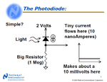
A reverse-biased photo diode leaks a tiny current when it is exposed to light. But R1 has a value that is so low that it connects the + input of the opamp in your schematic to the positive supply.
The inputs of an LM358 work properly only when they have a voltage from 0V in your single-supply circuit to 1.5V less than the supply voltage. So the photo diode should connect to ground and R1 should connect to the positive supply.
BUT the input bias current of an old LM358 opamp is too high (0.25uA max) for a 1M resistor to ground which would cause the input to be 0.25V when the photo diode is dark.

Then a Fet-input opamp can be used since its input bias current is almost zero but its inputs do not work at ground so it will need an additional negative supply voltage.

Your IR LED has a 10k resistor feeding it a tiny current so it will be fairly dim and might not be detected by the photo diode.

Here is how a photo diode works:
 

Attachments

  • photo diode.png
    photo diode.png
    111.9 KB · Views: 89

IR should not get coupled to the RX when they are kept near to each other. Confirm there is a proper isolation over there. Also you may need to tune it or calibrate it properly in this type of circuits. Try to play with the comparator reference using the trim pot.

i have seen the same circuit i am following in a development board of arduino uno... and actually i have copied my circuit from there..
and its working fine there

look these are the pics of the board part containing IR pair ckt... and the ir pair on the board works fine the out is connected to the 1 pin of lm358... i also tried it but it doesnt work.. in fact once a time when i was doing on breadboard when i connect the out to 7th pin.. the circuit works... but after 5 minutes it does'nt

https://obrazki.elektroda.pl/3319459100_1417672702.jpg
https://obrazki.elektroda.pl/2422126600_1417672703.jpg
 

Yes the circuit is fine and should be working. I saw that in the schematic you posted in the first post said that 10K is connected to the TX which must be 330E. If thaz 10K the circuit will not work. Next the LED connected at the output will be ON when an obstacle is detected. check 5 volts at Vcc pin of the IC in reference to the GND pin. The most interesting fault i saw is that you are using IR led of different appearance and color (one is transparent and other is dark blackish green) in your circuit at both sides which will never work. The Photo diode will be full black and fully opaque. Install that and come up with results.
Cheers and good luck
Pran
 

Like I said on the other website:
"The circuit schematic might work if the dual opamp is a TL082 that has inputs that work at its positive supply voltage.
The circuit does not have a 330 ohm resistor as you show.
I was correct, the Tx LED does not have low current from a 10k resistor, instead it has high current from a 220 ohm resistor."
 

Status
Not open for further replies.

Similar threads

Part and Inventory Search

Welcome to EDABoard.com

Sponsor

Back
Top