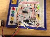
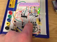
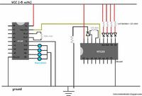
I cant get the Data LED's, at the decoder, to respond to my input from the encoder, any ideas? thanks. Pictures underneath...
I have recently purchased a few HT12E and HT12D ICs. i made a remote circuit using - letslearnelectronics.blogspot.in/2012/07/introduction-to-encoding-and-decoding_1610.html?view=sidebar
I have also been using holtek data sheets
HT12E - holtek.com/pdf/consumer/2_12ev120.pdf
HT12D - holtek.com/pdf/consumer/2_12dv120.pdf
I can get the valid transmission (VT) LED to energise and de-energise using a switch @ the TE pin on the encoder side of the circuit, or i can get it to permanently energise by connecting the TE pin to ground (active low) - this works as expected from reading both data sheets. However i cannot get the four LED's which are connected to the decoders data line to respond to the input from the encoder. They are permanently on. I have looked at many versions of this circuit online and they all seem to be the same. They all reccomend using switches on the data input @ the encoder.
Your messy breadboard shows a 9V battery connected to maybe a 5V regulator IC? The input and output capacitors should be ceramic, not electrolytic and should be connected very close to the regulator IC pins, not far away like you have.
The multimeter will not show high frequency oscillation, it will show an average voltage.
The capacitance of the scope's cable might stop any oscillation.
Why not make a 7805 regulator circuit the same as shown on EVERY datasheet of it?