gillani
Newbie level 3

Fm Transmitter
I was looking for a project to make for fun when i found this FM transmitter, i got curious because it is a best project for fun as well as you tube, it is a simple FM transmitter but i make it it the simplest. I replaced the variable capacitor with a fixed one, re-calculated its frequency to be able to tune it only by the coil instead of the variable capacitor.
This circuit design is unstable because its resonant frequency drifts off if you get your hands close to the antenna or the circuit, the length of the antenna affects the resonant frequency so you should fix it on a fix place so that its frequency remain constant.
Note: It is a very simple transmitter but its range can be 2 km if u attach long antenna with it.
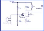
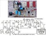
Circuit
single FM Transmitter
Components Required
https://envirementalb.com/simple-fm-transmitter
I was looking for a project to make for fun when i found this FM transmitter, i got curious because it is a best project for fun as well as you tube, it is a simple FM transmitter but i make it it the simplest. I replaced the variable capacitor with a fixed one, re-calculated its frequency to be able to tune it only by the coil instead of the variable capacitor.
This circuit design is unstable because its resonant frequency drifts off if you get your hands close to the antenna or the circuit, the length of the antenna affects the resonant frequency so you should fix it on a fix place so that its frequency remain constant.
Note: It is a very simple transmitter but its range can be 2 km if u attach long antenna with it.
Circuit
single FM Transmitter
Components Required
R1 : 100ohm resistor
R2 : 4.7 ohms resistor
C1 : 1nF ceramic capacitor
C2 : 47pf ceramic capacitor
Q : bc2655,2n222 or 2N3094
L : 212nH (5 turns of 15 gauge copper wire)
Mic : Condenser mic
Bat : 3v battery and its holder
Ant : Ideally a piece of wire, 1/4 or 1/2 of the wavelength of the frequency if you want more range then use roof antenna and adjust frequency to increase and decrease the space between inducter coil.
Note R2 : 4.7 ohms resistor
C1 : 1nF ceramic capacitor
C2 : 47pf ceramic capacitor
Q : bc2655,2n222 or 2N3094
L : 212nH (5 turns of 15 gauge copper wire)
Mic : Condenser mic
Bat : 3v battery and its holder
Ant : Ideally a piece of wire, 1/4 or 1/2 of the wavelength of the frequency if you want more range then use roof antenna and adjust frequency to increase and decrease the space between inducter coil.
6v battery can be used to increase the range of this transmitter
Circuit Diagramhttps://envirementalb.com/simple-fm-transmitter


