circuitspedia
Newbie

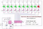
One colour of all LED remain fix and second colour of all LEDs in running mode one by one. This gives a very cool and interesting visual lighting effect. circuit is simple and no used any microcontroller .
In this LED blinker circuit 1 ic and 1 CD4017 used to produce counting output. 2 NOT GATE inverter IC used to Change the supply alternate For changing colour of LED by inverting the input supply on LED.

555 timer ic is used to create random clocked pulse signal for the changing the output through counter ic 4017. As you know that when the pulse signal at input pin 14 of ic 4017 get then according to each clock pulse changing , the output is on (High)one by one . The output of 4017 is starting from pin 3 (output 0), pin 2 (output 1), pin 4(output 2), pin 7 (output 3) and so on upto pin 11 (output 9 ).
All output of 4017 ic connected with NOT GATE inverter input and output of all inverter input is also connected with second pin of bicolour led. Not gate inverter is the logic that changed the signal from High to Low or Low to High. More circuits
Here Low means negative or 0 and High means positive or 1.
Gif
Click For more detail
Moderators received complaints from Edaboard users that the circuit doesn't work.
I just realized that this thread has the answer option disabled due to a technical forum problem. We'll try to fix it.
In this LED blinker circuit 1 ic and 1 CD4017 used to produce counting output. 2 NOT GATE inverter IC used to Change the supply alternate For changing colour of LED by inverting the input supply on LED.

555 timer ic is used to create random clocked pulse signal for the changing the output through counter ic 4017. As you know that when the pulse signal at input pin 14 of ic 4017 get then according to each clock pulse changing , the output is on (High)one by one . The output of 4017 is starting from pin 3 (output 0), pin 2 (output 1), pin 4(output 2), pin 7 (output 3) and so on upto pin 11 (output 9 ).
All output of 4017 ic connected with NOT GATE inverter input and output of all inverter input is also connected with second pin of bicolour led. Not gate inverter is the logic that changed the signal from High to Low or Low to High. More circuits
Here Low means negative or 0 and High means positive or 1.
Gif
Click For more detail
Moderators received complaints from Edaboard users that the circuit doesn't work.
It does not work since the 100 ohm resistors on the outputs of the ordinary CD4017 short the outputs to ground since the supply is only 5V then the output high current of the CD4017 is very low.
I just realized that this thread has the answer option disabled due to a technical forum problem. We'll try to fix it.
