vindhyachal
Newbie level 4

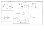
Comments/suggestions on ckt. Ckt is attached.
1. First section is Main with switch & MOV with EMI filter cap. It has MOV installed with fuse on line. Then switch is connected after which a EMI filter is used. Instead of one 1M resistor, I have now used two 500K resistor.
2. Second is zero cross detect ckt. Is it ok?
3. Third is +5V supply. I have checked this on breadboard. It is working giving +5Vdc at 50mA.
4. Fourth is MCU driving a triac using MOC3021. Since load is 100% resistive so I haven't used snubber circuit here.
5. Fifth is thermal fuse section. I don't understand how it works here. I have copied it from other board.
Load is a resistance with a isolated wire along along it.
The two ends of this wire are shorted & connected to J2 connector-thermal point. When load gets excessive heat up beyond safe point, the isolation gets punctured & this shorts load with wire. This leads to current flow in this wire & current flows through two parallel 4.7K resistor. Thermal fuse is placed in between these two resistor. After they gets heat up they blow the thermal fuse.
But how does this ckt works I don't understand

