Continue to Site

Welcome to EDAboard.com

Welcome to our site! EDAboard.com is an international Electronics Discussion Forum focused on EDA software, circuits, schematics, books, theory, papers, asic, pld, 8051, DSP, Network, RF, Analog Design, PCB, Service Manuals... and a whole lot more! To participate you need to register. Registration is free. Click here to register now.

[moved] AC voltage measurement using pic

Status
Not open for further replies.
Re: AC voltage measurement using pic

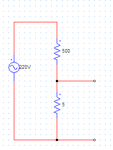
PIC .1.png

We can follow simple method by resistance divider 100:1, For 220V you may get 2.2V. Using PIC ADC convert this voltage and multiply by 100 you get exact voltage appeared on the source.
Be careful because 220V ground is connecting to microcontroller ground, If any safety issue you must use isolation transformer (Step down)
 

Re: AC voltage measurement using pic

Hi,

I prefer this:

AC_IN.png

* R1 and R2 form a 5k load referenced to the 1.2M input resistor R3. So it creates a voltage divider with 1.2M and 5k ==> gain = 1/239 = 0.00418.
* Additonally R1 and R2 make ADC input voltage lifted by VRef/2. With the used 3.0V Ref...the ADC input voltage moves around +1.5V
* R3 is the input part of a voltage divider. It must be rated for the AC input voltage and the expected power dissipation. (here only 40mW). (For safety reasons you should consider to use two resistors in series, each rated for the full AC input voltage). R3 limits the input current to safe 200uA
* C2 makes it possible that the ADC_voltage gets shifteg by VRef/2. Inieed it is a high pass filter with very low fc. The voltage across C2 usually is 1.5V DC, about no AC. But for safety reasons i recommend to use a X2 foil capacitor rated with your high AC input voltage.
* C1 is just a low pass filter to avoid high frequency noise at the ADC inputs.

Klaus
 
  • Like
Reactions: Astrodyne

    V

    Points: 2
    Helpful Answer Positive Rating

    Astrodyne

    Points: 2
    Helpful Answer Positive Rating
Re: AC voltage measurement using pic

Hi,

Can i use above circuit for three phase voltage measurement (or) tell me any changes in this circuit for three phase voltage measurement.

thanks
 

Re: AC voltage measurement using pic

Hi,

Yes. Just threefold the circuit.

Mind, that the ADC (microcontroller) GND needs to be connected to neutral (star point) of mains.

This is a non isolated solution! Take care about safety!

Klaus
 

Re: AC voltage measurement using pic

hi,

Hi,

Yes. Just threefold the circuit.

Mind, that the ADC (microcontroller) GND needs to be connected to neutral (star point) of mains.

This is a non isolated solution! Take care about safety!

Klaus

if i use the above circuit for three phase measurement, how can i write the code and tell me, what kind of measurement it takes like peak or RMS or average rectified??
 

Re: AC voltage measurement using pic

Hi,

Peak, RMS, average rectified:

What value do you need? I guess nobody can´t tell you. You need to decide.

And how do you want to measure/claculate it?
And what resolution, what precision and what accuracy do you expect?

****
Many people want to display RMS. But they do a number of ADconversions and find the peak value. Then they simply multiply them with 0.707 and think they have RMS.

But what they do is just an estimation about RMS. (they don´t calculate RoutMeanSquare).
And the result is only true if the input signal as a pure sine signal without overtones and without noise.
But how do they know that the input is pure sine? Either they KNOW it, or they use filters, or they just hope it.

Because they use only one of all of the sampled values they take all of the errors that is included in this single value. End even worse they most probably focus on a single value with excessive high error.
Errors like noise, switching peaks, distortion cause voltage peaks. The higher the error, the higher the peaks. And because they use the value of the highest voltage there is a good chance they choose the value with the highest error.

*****
RMS and rectified average value take ALL the samples into account and therefore the error is also averaged. Both are better than the single peak value measurement.

But rectified average depends on waveform. If the input ideviates from a pure sine, then the result contains some error. How much? Noboby knows. But definitely it´s far better than the peak method.

****
Therefore my recommendation: If you want to display RMS then you should measure and calculate RMS. It´s the most precise method. It is independent of waveform and it introduces about no error.
The calculated value is very accurate.

****
On the other hand for rectified average and RMS you need a fixed known sampling rate and you need some programming skills.
Both need some time and mathematics to calculate sampling frequency and so on..

***
In any case you should know the input signal it´s overtones, it´s noise and it´s errors... it´s behaviour in time.
And you need to know how often you need a result. Maybe once in 15 minutes, maybe 3 times a second, maybe every fullwave, maybe faster...

***

Now it´s on you to decide which way to go.


Klaus
 

Status
Not open for further replies.

Similar threads

Part and Inventory Search

Welcome to EDABoard.com

Sponsor

Back
Top