Continue to Site

Welcome to EDAboard.com

Welcome to our site! EDAboard.com is an international Electronics Discussion Forum focused on EDA software, circuits, schematics, books, theory, papers, asic, pld, 8051, DSP, Network, RF, Analog Design, PCB, Service Manuals... and a whole lot more! To participate you need to register. Registration is free. Click here to register now.

Motor current sense circuit problem

Status
Not open for further replies.

anve

Newbie level 4
Newbie level 4
Joined
Nov 17, 2014
Messages
6
Helped
0
Reputation
0
Reaction score
0
Trophy points
1
Activity points
113
Hi everyone,
I am new to this forum and its my first post.This site has provided me a better way of understanding electronics.Thanks for that.

The circuit I have designed is for tripping off the power to motor when excess current flows through it at the time of stalling.(see the attached schematic).

[*]The current flowing through the motor is monitored across a current sense resistor (shunt resistor 0.5 ohm)which is connected to the positive terminal of the op amp lm324.
[*]The voltage drop across the shunt resistor is of the order of millivolts which is amplified by the first stage op-amp and given to positive terminal of the second stage lm324 op-amp which is configured as a comparator.
[*]The comparator output is fed to the gate of the SCR 2N5063 which operates the relay.(Earlier I used BC547 instead of SCR for turning on the relay.The result was annoying relay chattering.So I switched to SCR)
[*]When the relay is operated the motor stops and the led glows.
[*]The relay remains ON until the power is reset.

The problem is

The SCR is turning at unwanted times like :
>Switching on the power supply.
>Changing direction of the motor.
>Sometimes it turns on before the stalling current is reached.

Addition of a capacitor as a negative feedback(shown in fig.) from output terminal to negative terminal solved the issue to some extend(i.e. sometimes it works properly).But still it doesn't give consistent results.

This is a simple design problem.Either I am doing something realy stupid or I am not doing something really smart.Either case I need your help on the following:

1)Identify the fault if any in the design and suggest a practical solution.
2)let me know if there is any standard design for current sense-&-turn-of-motor-on-stalling-using-relay circuit.


P.S.there are lot of micro controller based solutions for the problem.But for this particular project the circuit should be purely analogue(w/o uC).

Eagerly waiting for your valuable comments

Thanks in advance

Anve

- - - Updated - - -

hello again,
The circuit I uploaded had a small mistake. I'm attaching it again after the correction.

Thanks
Anve
 

Attachments

  • circuit.pdf
    10.8 KB · Views: 182
  • schematic.pdf
    10.7 KB · Views: 155

SCR is more complex to use than a transistor. They dont operate in the same way as transistors. I dont recommend using scr in place of txr unless you have indepth knowledge about them.
 
  • Like
Reactions: anve

    anve

    Points: 2
    Helpful Answer Positive Rating
Hi,

It needs time forthe current to increase, then it needs additional time to detect overcurrent. And itneeds additional time to activate the relay and switch off.
How much time do you estimate for it?

Why don´t you use a MOSFET to drive the motor?

Klaus
 
  • Like
Reactions: anve

    anve

    Points: 2
    Helpful Answer Positive Rating
Thank you Suhas anand and KlausST for your quick reply and valuable opinions.

SCR is more complex to use than a transistor. They dont operate in the same way as transistors. I dont recommend using scr in place of txr unless you have indepth knowledge about them.

Hi Suhas, I took SCR because when a gate voltage(pulse) is applied to this device it enters into conducting mode and will not turn off even if gate input is removed(unless we apply negative voltage across it or cut off supply from its anode),which was exactly what I wanted.I wanted the relay to be turned ON and remain latched once the over current is detected by the comparator.The SCR will be turned ON which in turn will turn ON the relay which stops the motor and continues stopping until I cut off the supply.As I mentioned in my post, instead of SCR first I tried a transistor (BC547), but during motor stalling the relay was chattering continuously and the motor won't stop right away.
I agree that SCRs are trickier to deal with than transistor(though they are nothing but NPN and PNP connected back to back) but personally I felt it solves relay latching requirement.Anyway thanks for your suggestion.


It needs time for the current to increase, then it needs additional time to detect over current. And it needs additional time to activate the relay and switch off.
How much time do you estimate for it?

Why don´t you use a MOSFET to drive the motor?

Hi Klaus,
The job of motor here is similar to tightening a screw.So as the tightening progresses the speed decreases and torque increases , drawing more current from the source.So basically I am using a push button switch to operate the motor and the motor is in some concealed container.So when the motor stalls at some point the safety relay should operate and cutoff power to motor so that even if I press the push button the motor wont turn.In my lab testing when I tried to stop the running motor(by applying pressure on the motor shaft using a player) the SCR turned on the relay and the motor stopped instantly say in a second or less(which is more than enough for the application).

The problem is performance is not consistent.SCR turns on when I switch on the circuit for the first time or change the direction of motor(I'm using a DPDT relay for changing direction of motor(not shown in schematic)).

By using MOSFET you mean to replace SCR with MOSFET I suppose and not the H-Bridge solution to drive motor (in that case also you need a low side current sense circuit similar to this to switch of motor at stalling). I have two MOSFETs currently available with me IRF 530N and IRF9530.I presume N channel will do the job.Will try it out.Thanks for the suggestion.
 

You may want to to think about some blanking / timeout
functions and logically gate the overcurrent trigger to any
latching protection functions. The conditions you list all
look like transient-normal to me. Either require a longer
duration of overcurrent (timer) or blank the current sense
circuitry for some machine-realistic period when a large
step-speed is commanded (accel or decel).
 
  • Like
Reactions: anve

    anve

    Points: 2
    Helpful Answer Positive Rating
The lead from the current shunt to U1a, is extremely sensitive to pick and hum loops. It should have at least a 1K in series, right at the amps input pin. Also the "earthy" end of R6 should be close to the current shunt earth. Between the +12V supply to the motor and the feed to the opamp there should be a 100 ohm resistor with at least 100MF decoupling to earth. Else voltage spikes from the armature will get on the Vcc line to the opamps and cause you all sorts of misery. There should also be a snubbing diode across the relay coil.
Frank
 
  • Like
Reactions: anve

    anve

    Points: 2
    Helpful Answer Positive Rating
Thanks dick_freebird and chuckey for your valuable comments.
You may want to to think about some blanking / timeout
functions and logically gate the overcurrent trigger to any
latching protection functions. The conditions you list all
look like transient-normal to me. Either require a longer
duration of overcurrent (timer) or blank the current sense
circuitry for some machine-realistic period when a large
step-speed is commanded (accel or decel).
To be honest I know you have said something important in professional electronics design terms,but I couldn't understand it fully.If you explain in terms of electronics components maybe it helpful for me to understand.Thanks for the reply though.

The lead from the current shunt to U1a, is extremely sensitive to pick and hum loops. It should have at least a 1K in series, right at the amps input pin. Also the "earthy" end of R6 should be close to the current shunt earth. Between the +12V supply to the motor and the feed to the opamp there should be a 100 ohm resistor with at least 100MF decoupling to earth. Else voltage spikes from the armature will get on the Vcc line to the opamps and cause you all sorts of misery. There should also be a snubbing diode across the relay coil.

Hi Frank, In the full ckt the supply to the motor is from LM317 and supply to LM324 is from LM7812 as shown in the attached figure.Separate ground wires are drawn from battery for both the regulators
thinking that the disturbances in the motor loop won't affect the other components.

The shunt resistor earthy end is connected to LM317 ground.Thanks for pointing out that missing series resistor from shunt and input terminal of opamp. I have included that in the full circuit diagram attached with this comment.Initially I didn't upload the full circuit since I thought it will create confusion.The free wheeling diode across the relay have already been taken care.Forgot to draw it in the first circuit.
Now the decoupling capacitor.It seems a good solution to avoid noise.
Where to keep it in the new circuit? At the junction where push button and R10 meets?

So in the project there are 4 such motors and each I can select with the rotary switch.(M- is given as common to all motors only M+ is switched)
I can change the voltage input to those motors and direction using the DPST switch.

Please review the circuit and give some remarks.
 

Attachments

  • schematic_v2.0.pdf
    18.1 KB · Views: 137

You might want to put the 'scope to the current sense point
and see what the nature of the waveform is, under these
problem conditions.

Abrupt changes to armature voltage can shoot some current
through the winding capacitance which the inductance will
not allow classically / in the longer term, but which could
bother your current sense comparison. This is why almost
every current mode controlled PWM has built in leading edge
blanking. There will always be some "crud" superimposed on
the "real" current. You need to get past that without over-
reacting, yet react quick enough to be stable and to protect
the machine if there is a fault.

The next layer is stall / hard acceleration transition. Here
the current will be higher than the applied external mechanical
load would produce, until the rotor comes up to speed. This
is not the electrical current shoot-through, but inertia and
operates at that kind of timescale. If hard accel / decel is
in the plan, you want to understand how long a worst normal
case would need to get it done, vs how long a locked rotor
event can be fed max power before the varnish commence
to stank. Then either raise the duration of "fault" overcurrent
sensed, to trigger, or perhaps use some proxy for demanded
torque or delta-speed to subtract from the sensed current
value (or raise the reference value) when things are being
done deliberately.
 
  • Like
Reactions: anve

    anve

    Points: 2
    Helpful Answer Positive Rating
Your comparator (opamp) is missing a little hysteresis. Hysteresis will cause the comparator to suddenly switch its output when the input voltages are almost the same. Without hysteresis than a comparator will probably oscillate when its input voltages are almost the same.

Hysteresis is positive feedback and can be made by connecting a 1M resistor from the output pin 7 to the input pin 5. Try different values down to about 47k ohms.
 
  • Like
Reactions: anve

    anve

    Points: 2
    Helpful Answer Positive Rating
There are a lot of issues with your design and lack of specs to define exactly the behaviour in Current vs Time to trip is most important as well as immunity from false trip. I gather you want manual intervention to reset the trip.

Assuming this is what you want, a much simpler solution is to use a PTC current limiter and an SCR latch to force a MOSFET switch off.

Choose any holding current. https://www.digikey.com/product-sea...ee=0&rohs=0&quantity=&ptm=0&fid=0&pageSize=25
 
  • Like
Reactions: anve

    anve

    Points: 2
    Helpful Answer Positive Rating
You might want to put the 'scope to the current sense point
and see what the nature of the waveform is, under these
problem conditions.Abrupt changes to armature voltage can shoot some current
through the winding capacitance which the inductance will
not allow classically / in the longer term, but which could
bother your current sense comparison. This is why almost
every current mode controlled PWM has built in leading edge
blanking. ..................................
..........................................
Then either raise the duration of "fault" overcurrent
sensed, to trigger, or perhaps use some proxy for demanded
torque or delta-speed to subtract from the sensed current
value (or raise the reference value) when things are being
done deliberately.

Thanks for the explanation. LEB is new to me.From what I understand from leading edge blanking(after quick googling) is, a turn-On spike may occur when switching on the MOSFET or transistor which is driving our load(motor).At the beginning of each switching pulse(PWM pulse) the current limiting comparator is disabled for a fixed time to avoid premature termination.It seems a good solution but (correct me if I am wrong )is it applicable only to those cases where we are driving the motor using PWM? In my circuit I am not using PWM.Also if LEB can be implemented here please tell me how to implement preferably with a rough sketch(if it is not too much to ask for).

As for the hard accelration/stall transition part.I am using a 0.6A,10rpm high torque DC geared motor.I will check the details you mentioned using a DSO.As for now I am adjusting the pot(which sets the reference voltage)at the negative terminal of the op-amp to set at what point the SCR has to be triggered .i.e. if I am increasing the ref voltage the tripping action will be delayed once stalling(>1A drawn from source)is detected.


Your comparator (opamp) is missing a little hysteresis. Hysteresis will cause the comparator to suddenly switch its output when the input voltages are almost the same. Without hysteresis than a comparator will probably oscillate when its input voltages are almost the same.

Hysteresis is positive feedback and can be made by connecting a 1M resistor from the output pin 7 to the input pin 5. Try different values down to about 47k ohms.

Thanks for the suggestion audioguru.I have already tried Postive feedback hystersis using 1M resistor while I was trying out with BC547 to turn ON the relay.But haven't tried after switching to SCR. Will try it again with SCR and by changing resistor values.Theoretically it makes sense to add hystersis to suppress the sudden spikes in comparator.Lets's see.

There are a lot of issues with your design and lack of specs to define exactly the behaviour in Current vs Time to trip is most important as well as immunity from false trip. I gather you want manual intervention to reset the trip.

Assuming this is what you want, a much simpler solution is to use a PTC current limiter and an SCR latch to force a MOSFET switch off.

Hi SunnySkyguy , PTC seems to be a viable solution.It was not readily available at the local electronics store here last time I checked.So I ruled it out.But yeah, I can order through elements 14 or some other site(which taked more than 3 weeks to get it delivered here).I can manage to get it somehow.So this device is connected series to the power source and the load.
Can you please explain possibly with a circuit diagram how to use PTC + SCR lach + MOSFET in the current schematic (rough sketch is enough).Thanks
 

The LEB concept is applicable to any current-sensing /
current-limiting scheme; general purpose PWMs have
been driven to provide it by the needs of power supply
designers, but there's not a whole lot of difference other
than the dynamics, between driving one kind of inductor
and another.

You might find that you need a different timescale than
a fast switching power converter (like, they need pulse-by-
pulse, maybe your "pulse" is some number of half-cycles
and pertains more to rotor inertia than interwinding
capacitance, and so on. But the approach might lead you
somewhere.
 
  • Like
Reactions: anve

    anve

    Points: 2
    Helpful Answer Positive Rating
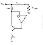
High side sensing Op Amps are needed for accurate sensing and you can get all this in one package for about 25 cents with the FAN4010 high side sensor IC. Then you can apply any safe operating method of detecting power or stall condition by integrating current* voltage product or just use a Polyfuse.

hi side I sense.png
 
  • Like
Reactions: anve

    anve

    Points: 2
    Helpful Answer Positive Rating
Hi all,

Sorry for my late reply.Got busy with some other work and got back to my problem with the circuit couple of days before only.
With all your good suggestions and solutions I was able to solve the problem.I'm posting my new circuit diagram.I wont say it is the perfect solution.But at least it works fine for my application.I am attaching my final circuit so that it may help some one facing similar problems.

In short two capacitors and two resistors solved the mystery.Here is how:

1) I studied the signal output across the shunt resistor and the output of first stage amplifying op amp using a DSO.It was noticed that,a lot of spurious noise signal was associated with shunt resistor voltage.While motor load was connected the voltage across shunt varied from 70mV to 100mV and was not a constant.Also there were sudden voltage spikes at power on which produced a high output at the second stage comparator op amp which operates the relay.
The voltage fluctuation must be caused by the AC component which ride over DC signal causing noise. Therefore, a bypass capacitor is needed to dampen the AC or noise present at all frequencies.I added one 10uF between the amplifier and comparator and one 1uF between the output of comparator and SCR gate(shown in schematic). It solved the problems to a great extend

2) Adding a 1K ohm series resistor between shunt resistor and non inverting terminal of amplifier and 1Mohm positive feedback resistor between the output and non inverting terminal of the comparator added further stability(0.47uF negative feedback capacitor in initial ckt was removed ).

Also I changed the shunt resistor value from 0.5 ohm to 0.1 ohm and the feedback gain of amplifier from 22 to 47.

3) To my surprise with all these modifications, the circuit worked even when I replaced SCR with BC547 to turn on the relay.And the annoying relay chattering was gone.But I preferred to keep SCR because if I am using BC547 I have to set the reference voltage at a lower level compared to SCR. Also SCR gave a faster response on motor stalling.

4)Made one PCB based on this circuit and is working fine.

Thanks for all your prompt replies and good suggestions.I am marking this thread as solved.:thumbsup:
 

Attachments

  • schematic_v3.pdf
    18.6 KB · Views: 145

I suspect you get a lot of ground shift noise between motor ground shunt and ground sense. The dynamics of this over complicated scheme causes much latency and opportunity for false trips.

Common mode noise poor rejection is another issue and a suitable CM choke would also help.

Layout issues not shown may point out even more opportunities.

Since ESR of motor drive and current shunt with coil resistance determines stall current while rotational inertial determines duration of stall current on startup, it might be better to control a soft start or jog start, or ramp start , rather than a primitive over-complicated stall protection scheme. Or better yet design all the motor parameters for power & speed control to ensure suficient power spurce is available to handle desired load.
 

I notice that your LM317 resistors are completely wrong. The 1k resistor from its output to its ADJ pin should be 120 ohms, not 1000 ohms to prevent the output voltage rising when there is no load (as explained in its datasheet).
 

Status
Not open for further replies.

Similar threads

Part and Inventory Search

Welcome to EDABoard.com

Sponsor

Back
Top